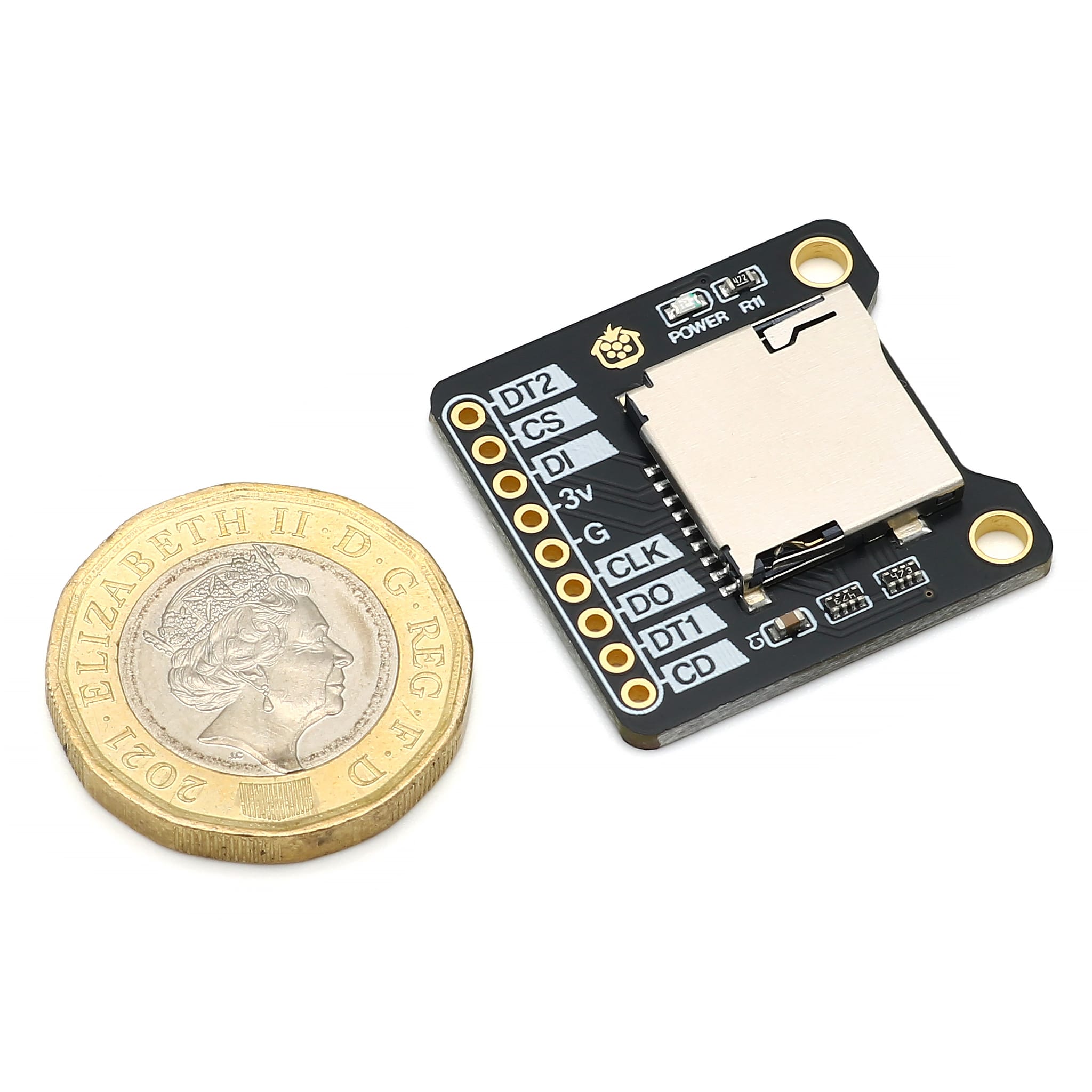
MicroSD Breakout
Price:
Sale price
£3.30
Stock:
Quantity:
Login / Signup
Cart
Your cart is empty


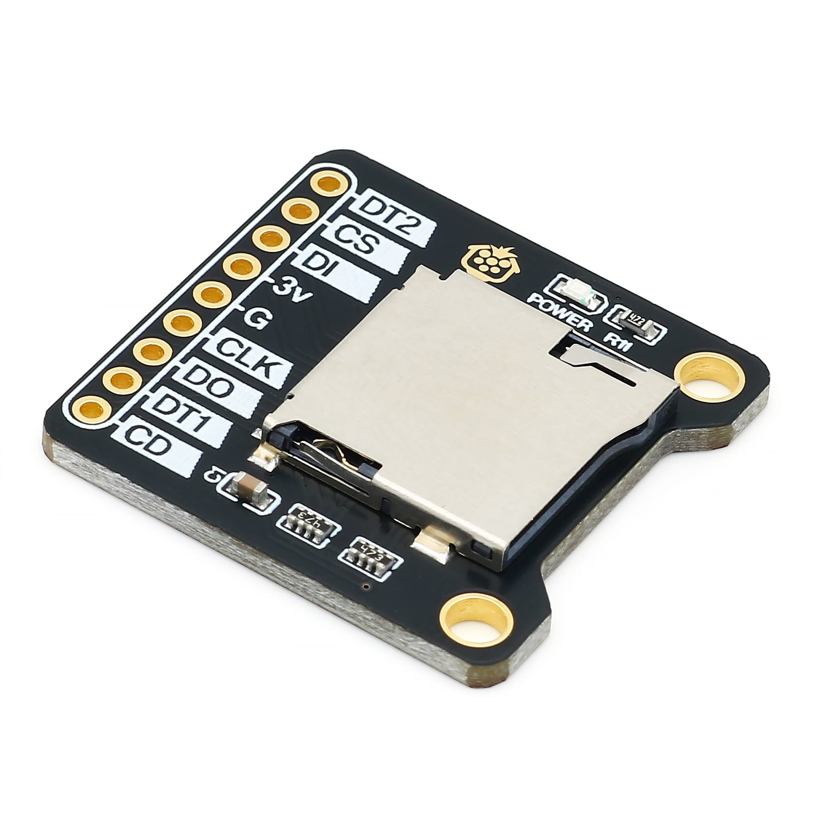
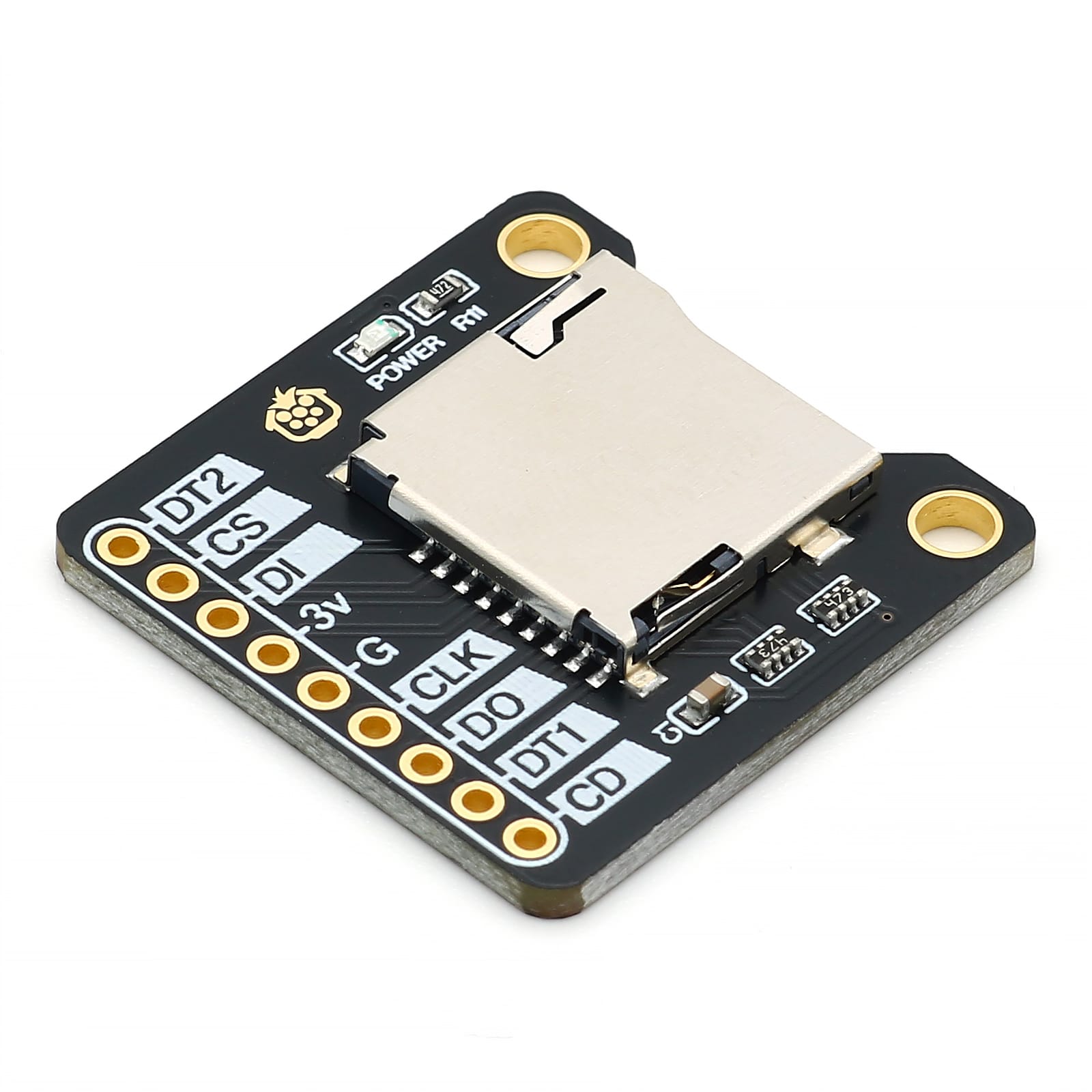
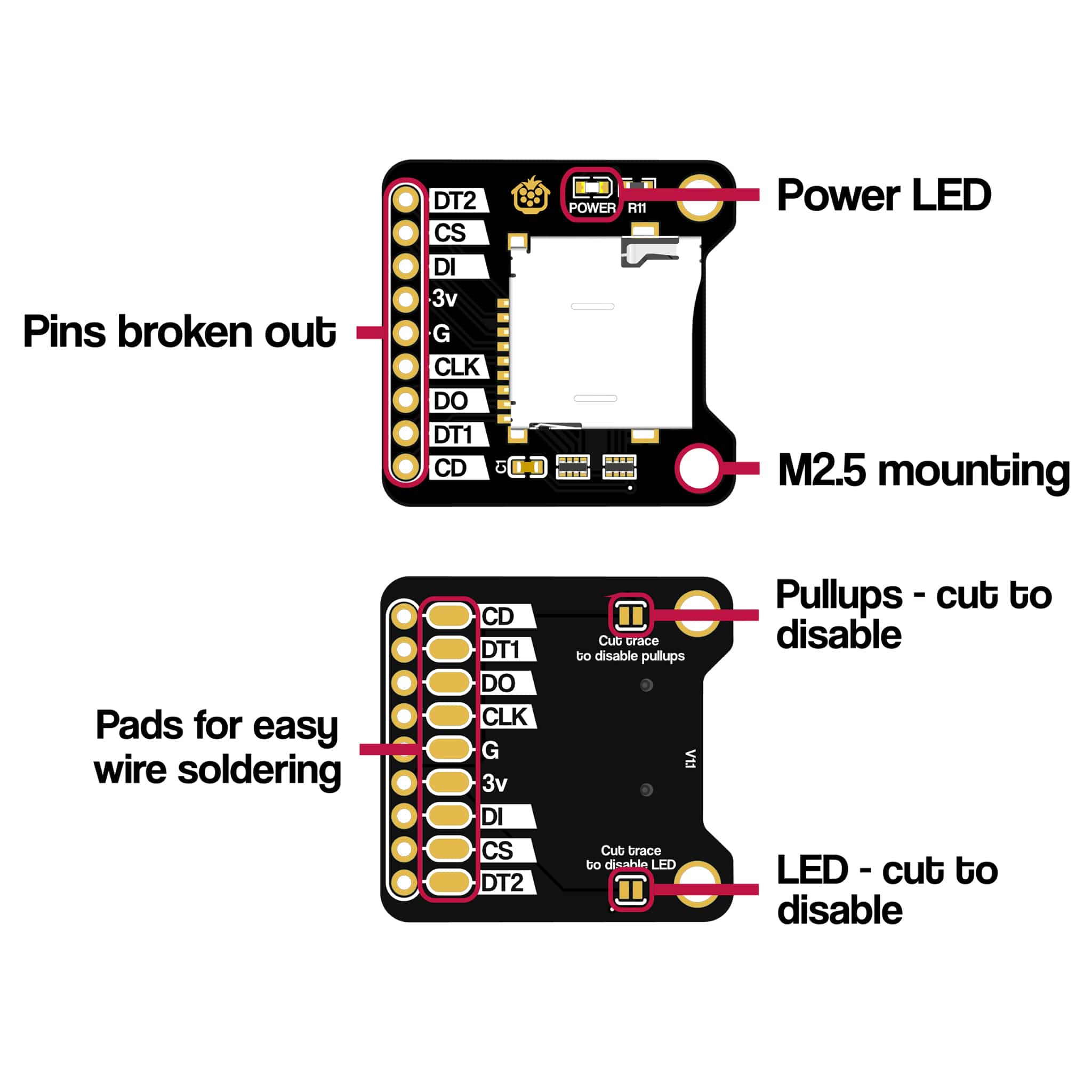
If your microcontroller doesn't provide any storage options, our MicroSD breakout can help! The breakout allows you to connect MicroSD storage to your 3.3V microcontroller in fast SDIO mode or simple (but slower) SPI mode, with the flexibility to solder wires, headers and more, alongside M2.5 mounting options, underside soldering pads, power LED and cuttable configuration traces!
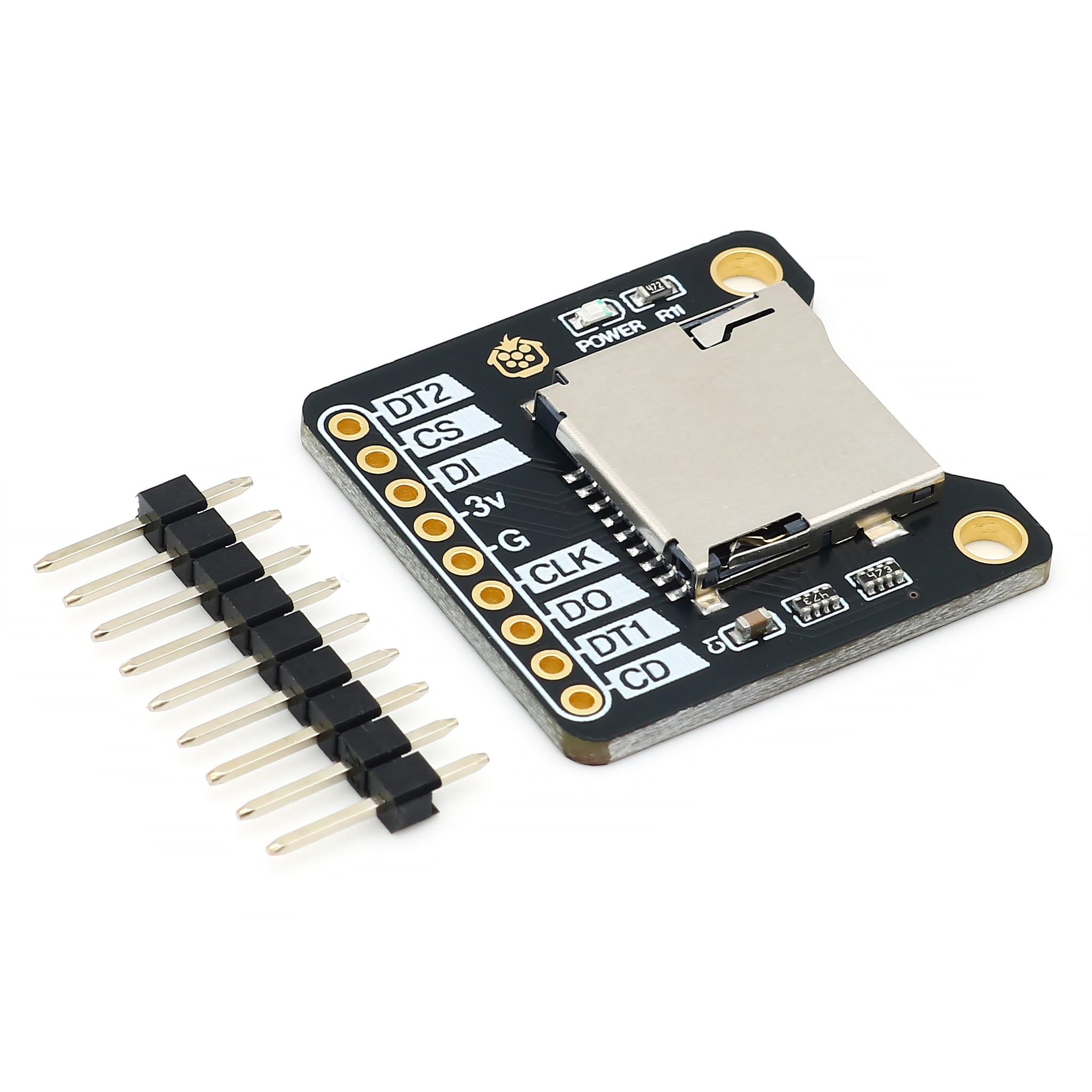
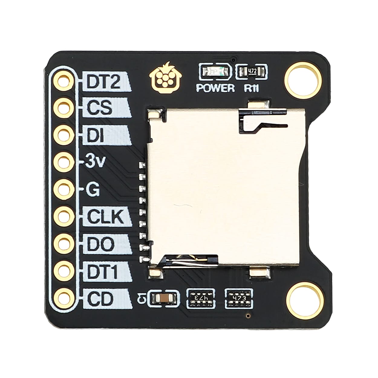
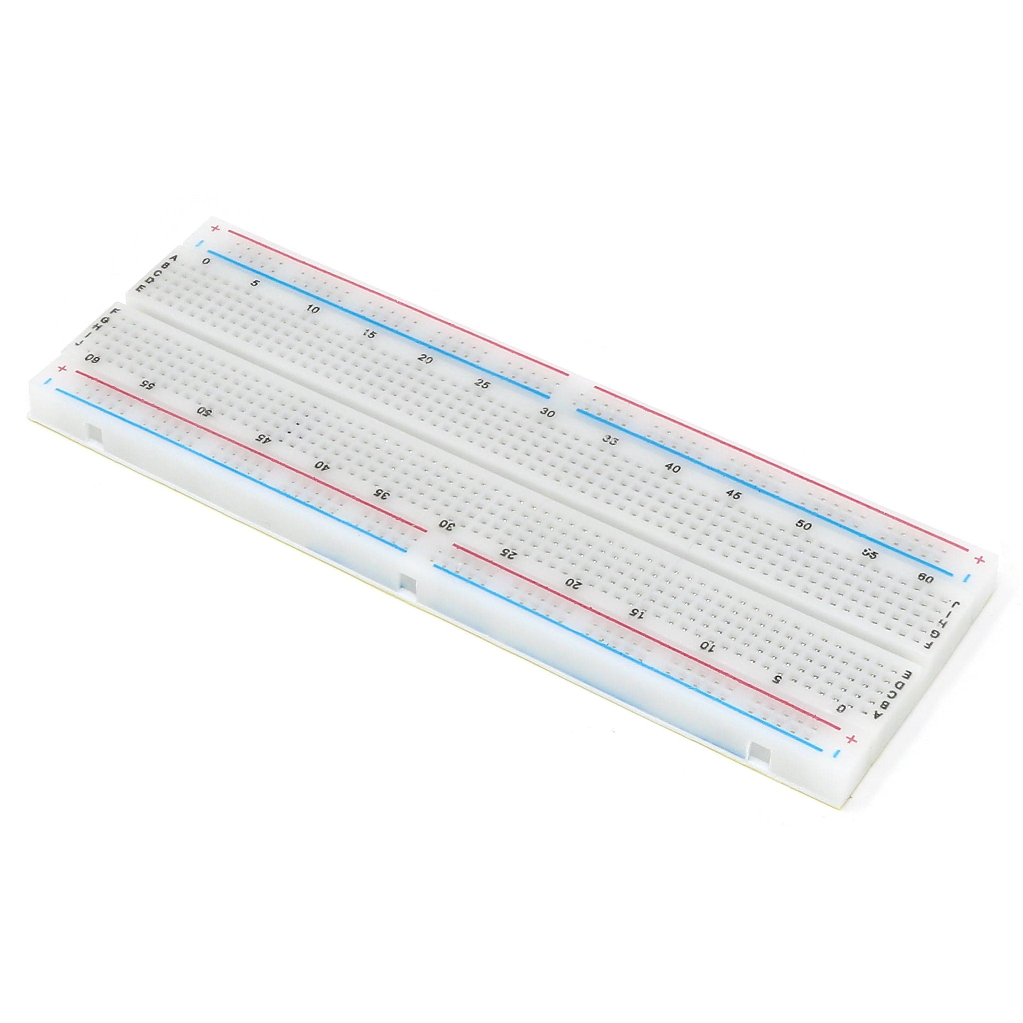
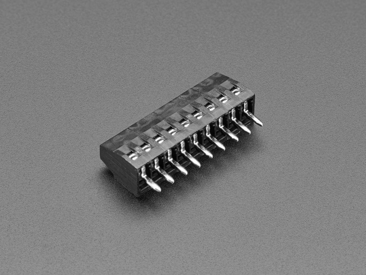
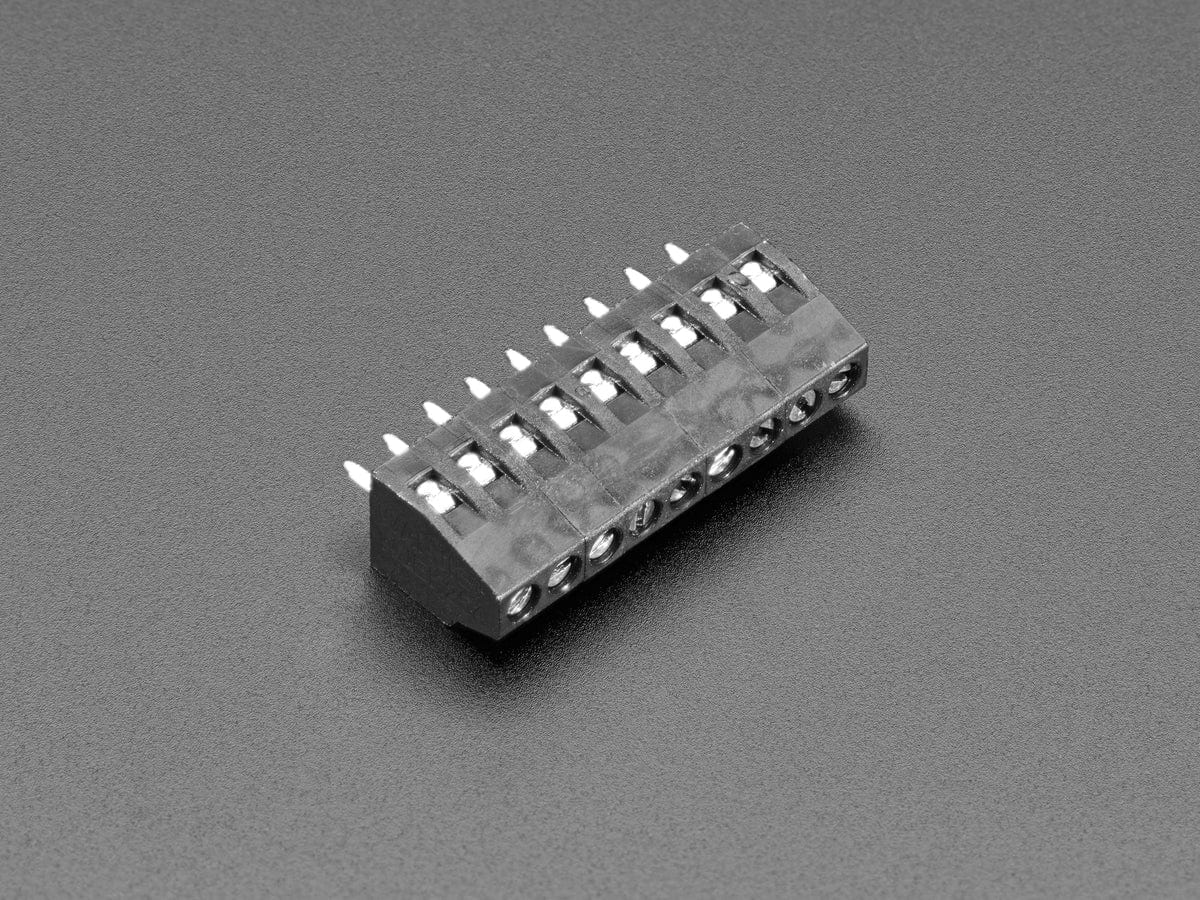
Each pin from the MicroSD slot is broken out to clearly labelled 2.54mm-spaced pads. You can solder whatever you like to these, such as the included 9-pin 2.54mm header strip (great for breadboard usage), some prototyping wire, or even an 9-way 2.54mm terminal block.
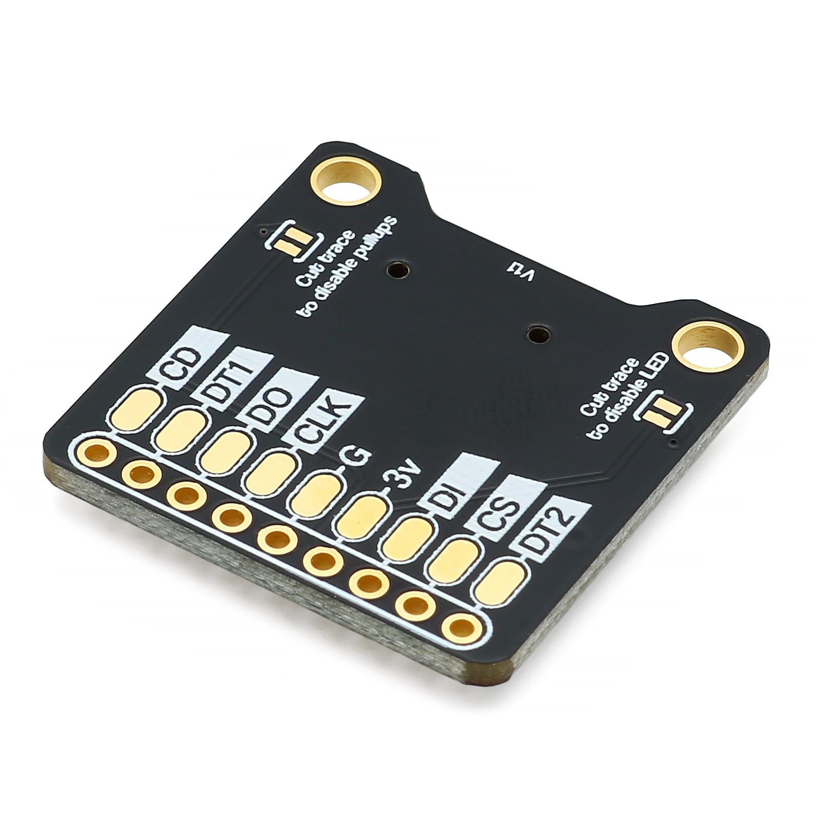
If you're soldering wires, consider using the underside solder pads. We added these because we know just how tricky it is to de-solder and re-solder a wire from a pad hole. With the underside pads, it's much, much easier to re-work and re-use.
On the underside of the board, you'll find two cuttable traces. One disables the onboard LED (if you're not into the blinky life) and the other disables the pullups (just in case your dev board has pullups on the pins you're using already).
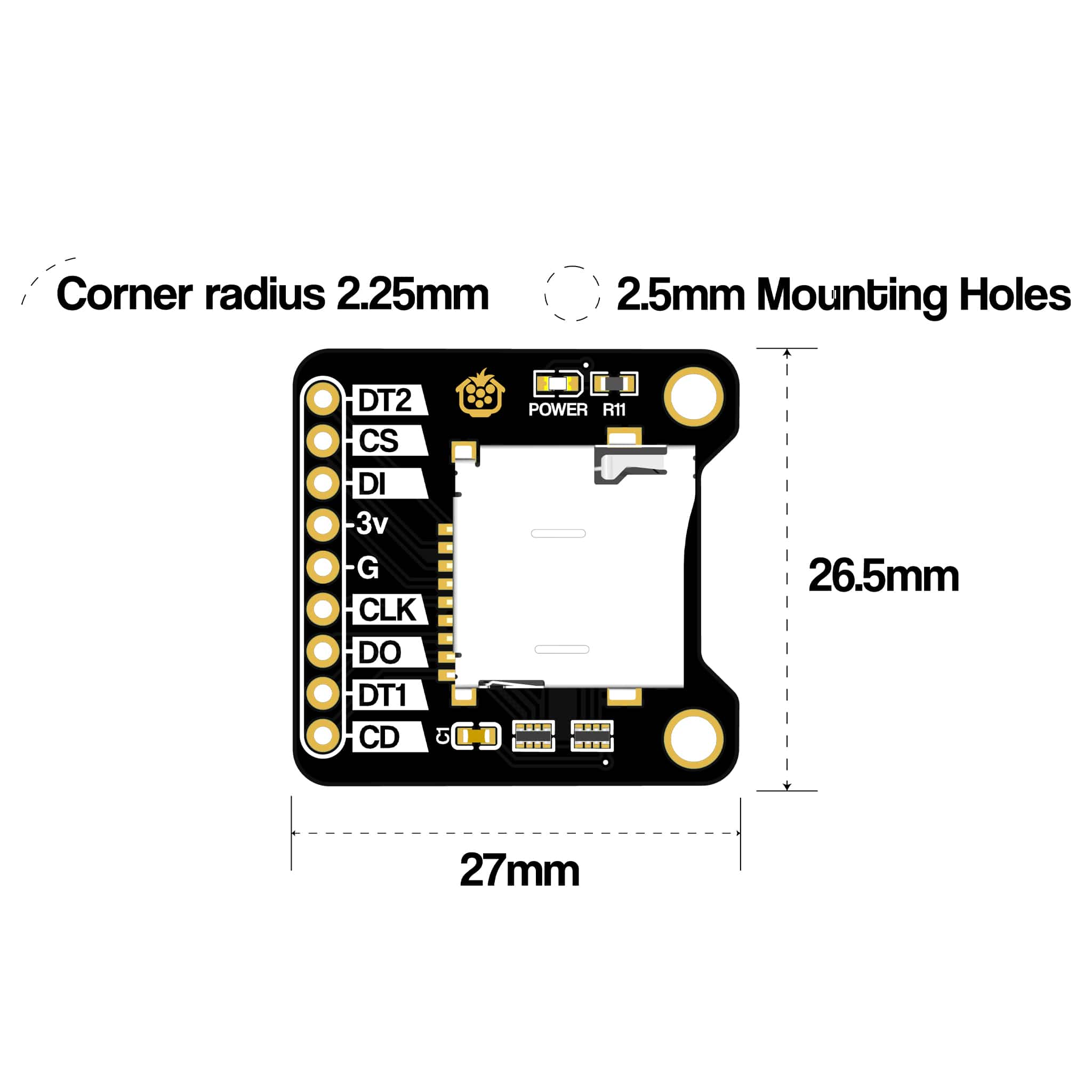
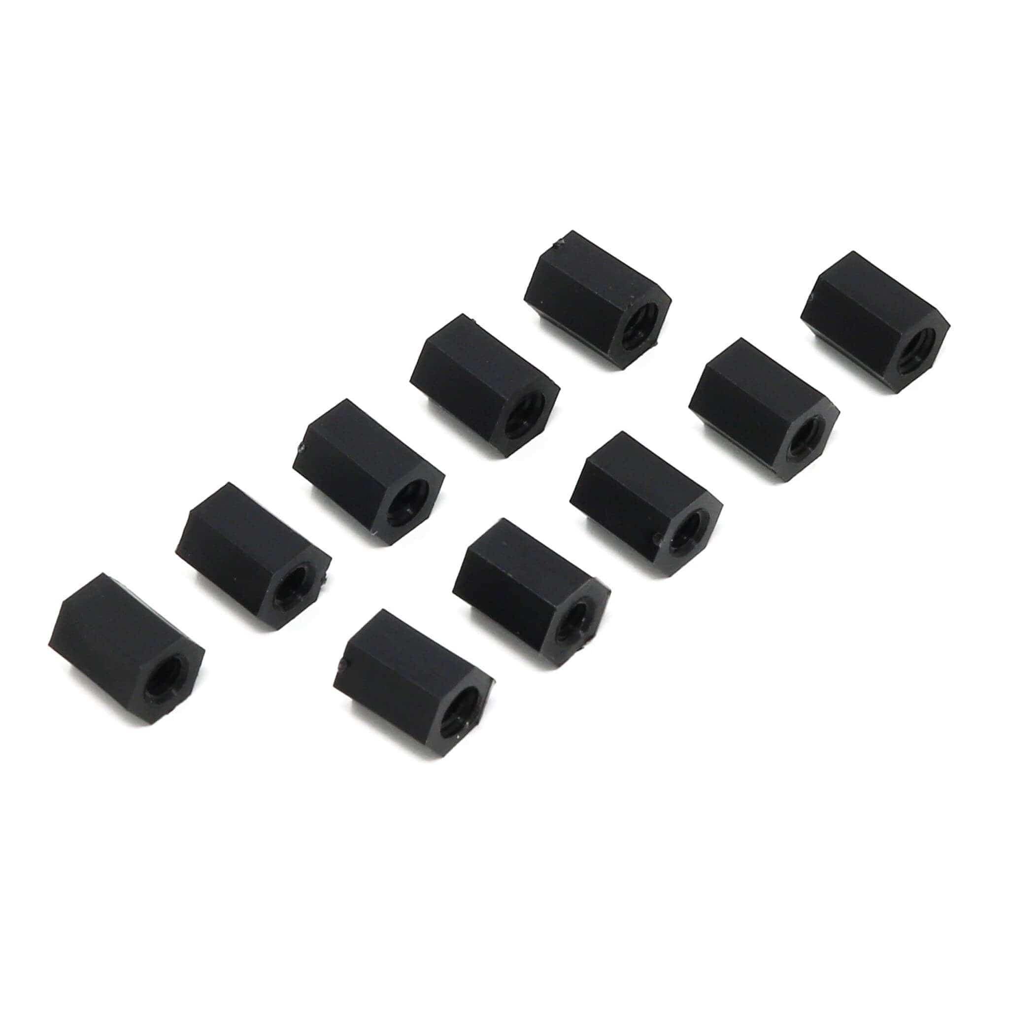
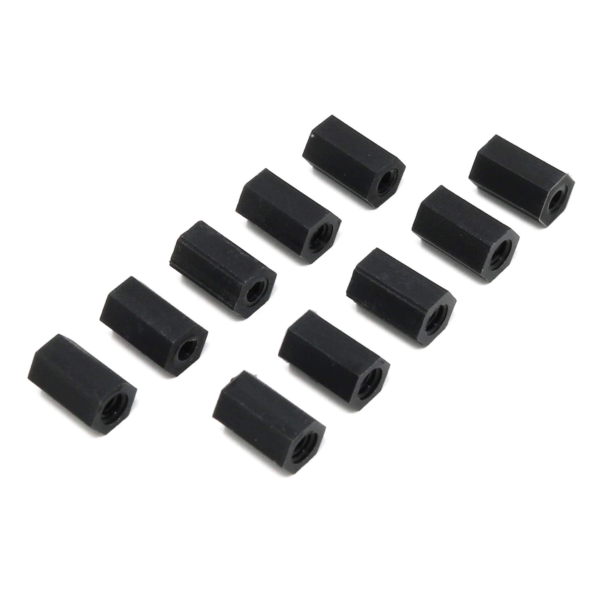
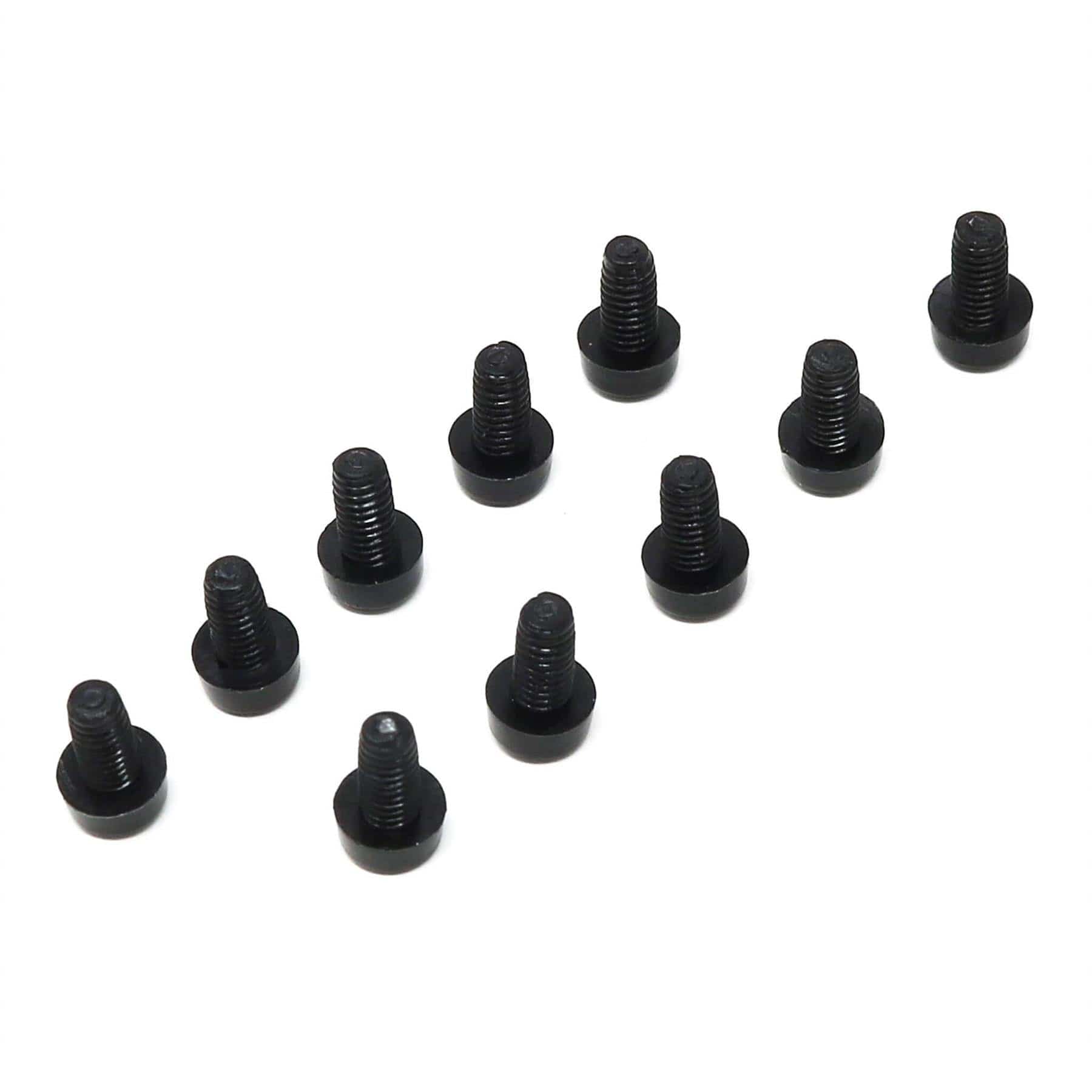
We also used M2.5 mounting holes as they're a popular size with easy-to-source fixings...and because we despise fiddly M2 fixings.
You can choose to run this in SDIO mode or SPI mode:
We provide example ESP32-S3 code for Arduino IDE for both of these modes in our resources section (below) for use with an ESP32-S3.
🤏 Compact 3.3V MicroSD breakout to add storage to microcontroller projects
📌 MicroSD pins broken out to clearly labelled 2.54mm pads
↩️ Underside solder pads for easy wire soldering and re-work
💡 Blue power LED for visual indication (can be disabled via cuttable trace)
🔪 Cuttable traces to disable the onboard LED and/or the pullup resistors
🔩 M2.5 mounting holes for fiddly-free mounting
🪙 ENIG (Gold) PCB plating for oxidation resistance and durability
💸 9-pin 2.54mm male header strip included!

Example code (for Arduino IDE):
Please note that the corner radius may vary due to the manual PCB finishing process

Your payment information is processed securely. We do not store credit card details nor have access to your credit card information.