
Login / Signup
Cart
Your cart is empty
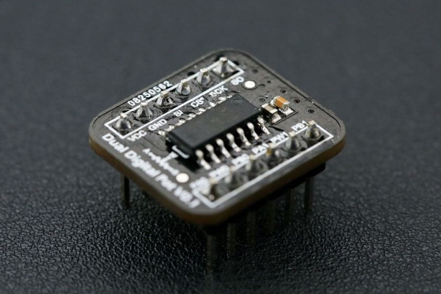
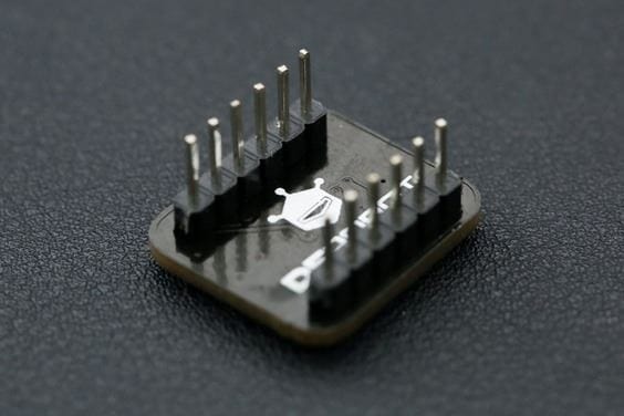

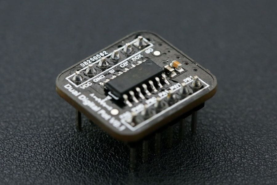
Digital potentiometers are also called "Digital Pots" in short. It is a kind of mixed-signal IC, which is able to dynamically change the internal resistors through MCU like Arduino. It can be applied to applications such as LED DC dimming, linear stable voltage source, oscillator, low pass filter or differential amplifier.
This breakout employs MCP42100 internally manufactured with two individual 100K digital pot. It features small dimension and low power consumption.
With our tutorial and sample code provided, you can quickly apply this module to your project. Compared to the traditional mechanical potentiometer, the digital pot features as flexible (program control), small size (ICs) and high reliability (without mechanical parts). It can replace the traditional option in many applications. Digital pot is usually used to change the sound volume in audio devices, such as smart loudspeaker, cell phone, and music player.
In addition, with a proper design op-amp circuit, the digital pot can also be applied to change some key parameters of the circuit dynamically, such as LED DC dimming (output current), a linear stable voltage source (output voltage), oscillator (frequency and amplitude), low pass filter (bandwidth) and differential amplifier (gain).
This breakout employs MCP42100 internally manufactured with two individual 100K digital pot POT0 and POT1. Each pot has 256 taps with a resistor of 100KΩ. It supports a wide voltage supply (DC 2.7V - 5.5V) compatible with MCU of 3.3V and 5V.
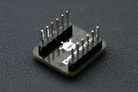
The breakout features as small size (20.0mm*18.0mm) and reserves the SO pin for multiple breakouts being configured in daisy-chain connection. If you have a I/O shield in hand, this breakout can be easily connected to it with the attached 5 pin male to male cable.
Two triangular waves out of phase can be observed from the oscilloscope. If we zoom in a section of the wave, the triangular wave is actually made up of many steps. Each steps correspond to one wiper position. The width of the step is about 1ms, because the program delay for 1ms between every wiper changes. The upstairs half cycle and the downstairs half cycle consist of 256 steps each, therefore the period of the triangular wave is 256*2=512ms.


