Login / Signup
Cart
Your cart is empty
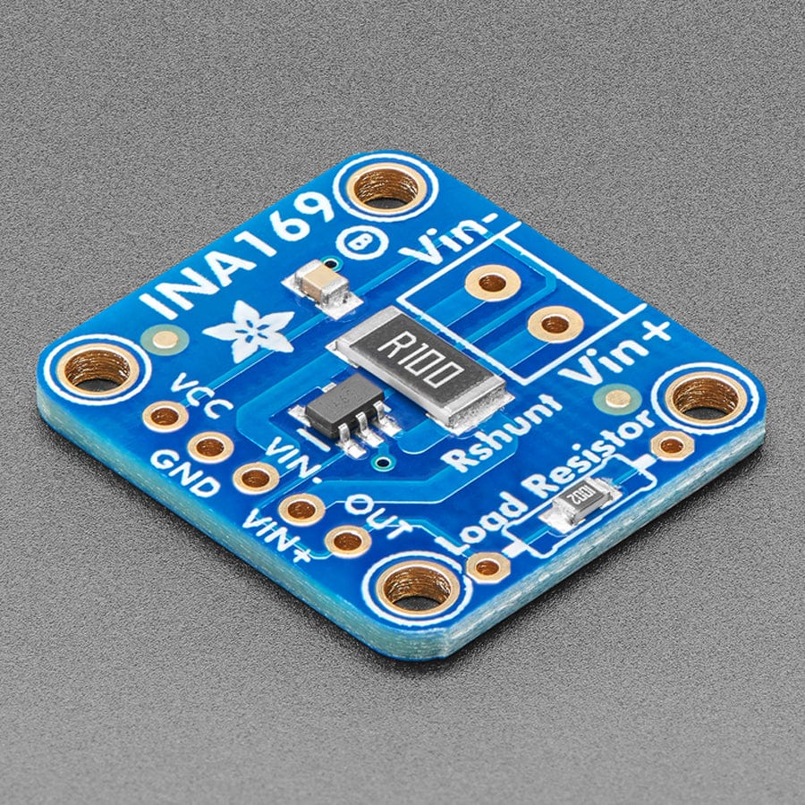
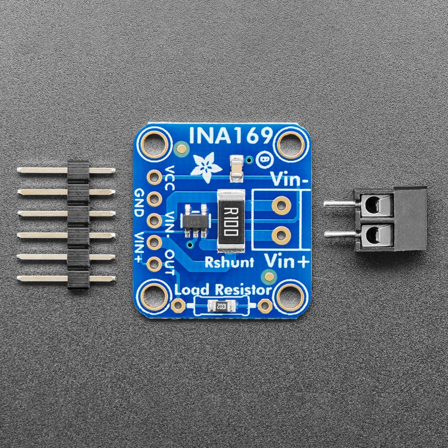
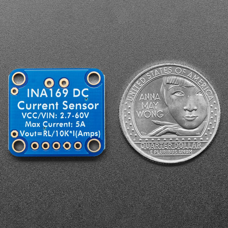
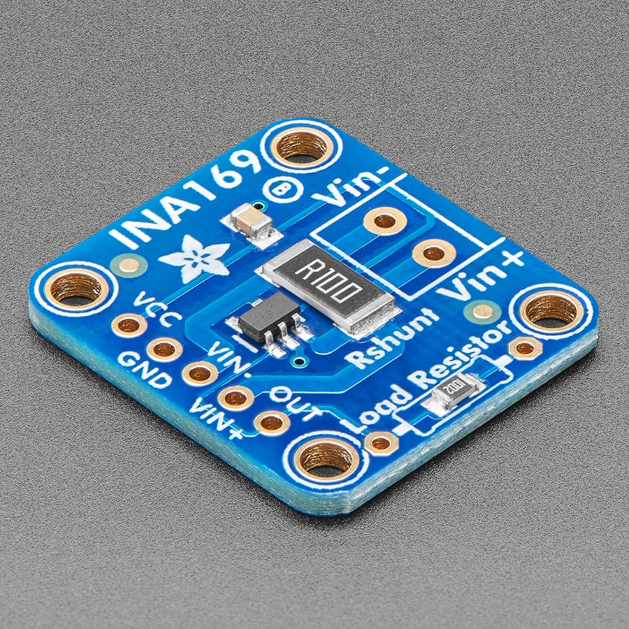
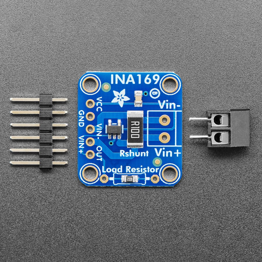
This breakout board will solve all your current monitoring problems. Instead of struggling with a multimeter, you can just use the handy INA169 chip on this breakout to both measure both the DC current draw and have a handy analogue output that is with respect to ground. The analogue output makes this an ideal breakout for feedback-loop control.
Most current-measuring devices such as our current panel meter are only good for low-side measuring. That means that unless you want to get a battery involved, you have to stick the measurement resistor between the target ground and the true ground. This can cause problems with circuits since electronics tend to not like it when the ground references change and move with varying current draw. This chip is much smarter - it can handle high-side current measuring, up to +60VDC!
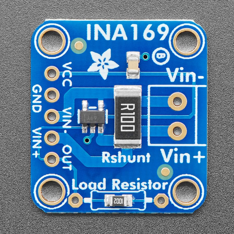
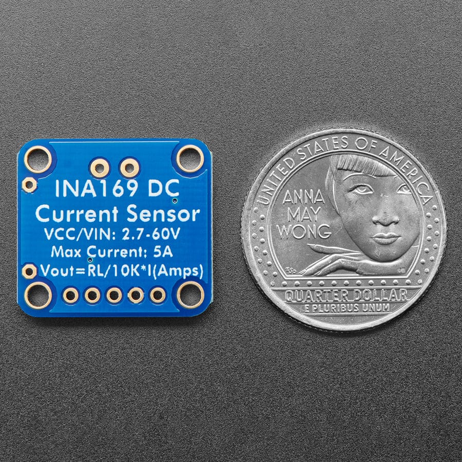
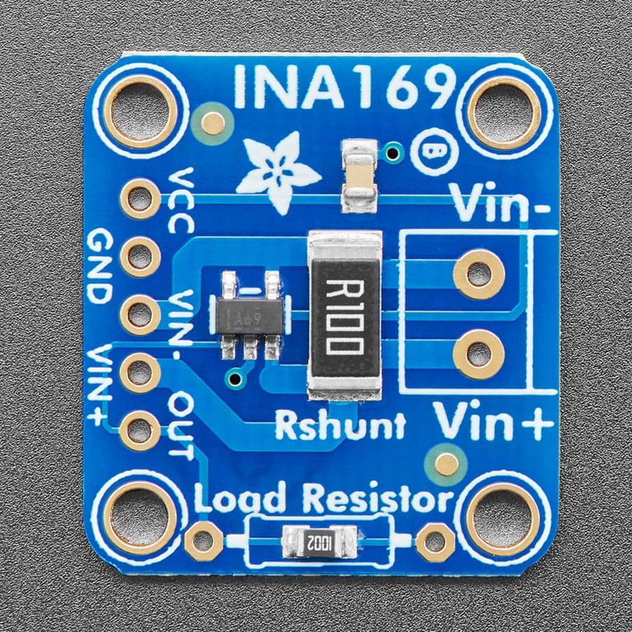
A precision amplifier measures the voltage across the 0.1 ohm, 1% sense resistor. The resistor is rated for 2W continuous so you can measure up to +5A continuous. The output is a current that is drawn through the on-board 10K resistor so that the output voltage is 1V per Amp. So for the 2A draw, the output will be 2V. You can change out the load resistor to be larger or smaller by cutting the traces next to it and soldering a thru-hole resistor over. If you solder in a 20K resistor you'll get 2V per Amp, with a 5K resistor, 0.5V per Amp.
We include a 5-pin header (so you can easily attach this sensor to a breadboard) as well as a 3.5mm terminal plug so you can easily attach and detach your load. Usage is simple. Power the sensor with 2.7-60V to VCC, and connect V+ to the high side of your power supply, then connect V- to your grounded load. Then use a multimeter to measure the voltage output, that's it!
Note: The terminal block included with your product may be blue or black.
As of July 15, 2024 – we've updated this PCB with Adafruit Pinguin to make a lovely and legible silkscreen - you may get the new PCB or the older version with vector fonts - both are identical other than the fancy silkscreen.


