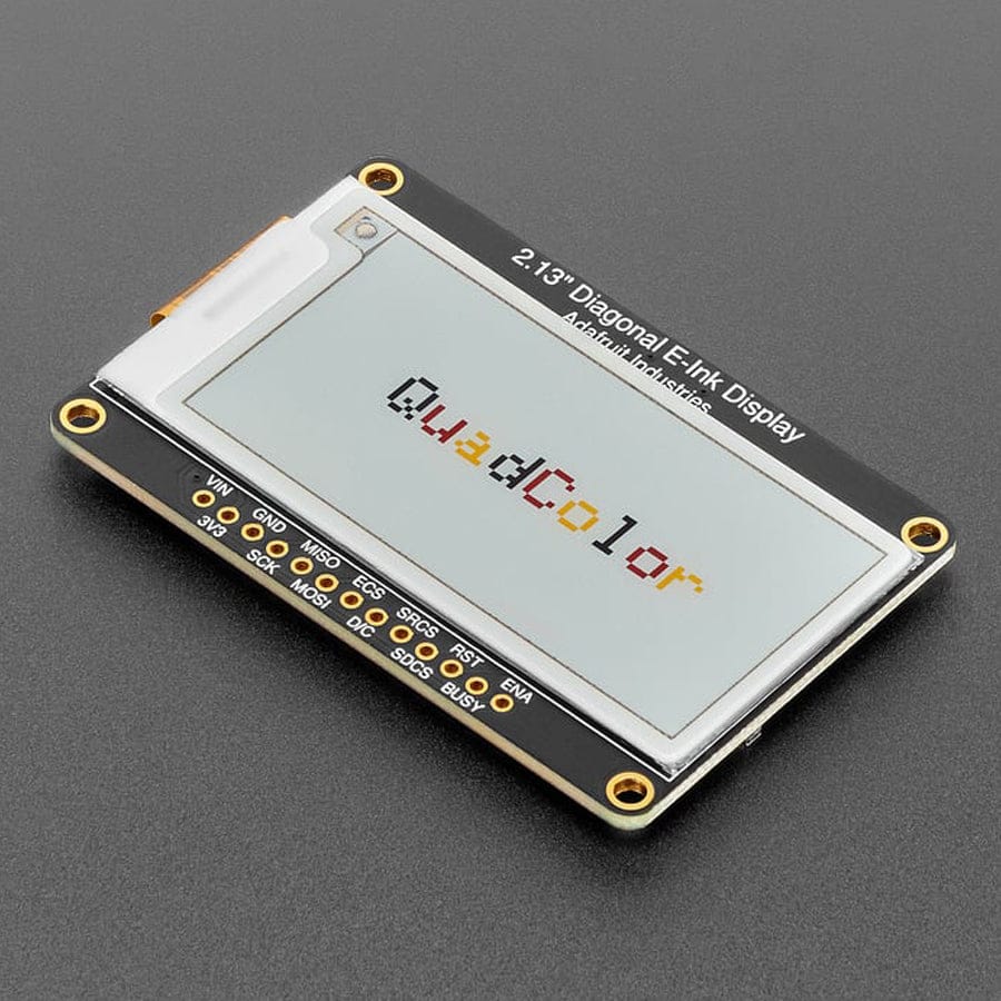
2.13" (250x122) Quad-Colour eInk / ePaper Display
Price:
Sale price
£19.20
Stock:
Quantity:
Login / Signup
Cart
Your cart is empty


This 2.13" quad-colour ePaper breakout makes eInk easy on microcontrollers, with onboard SRAM and microSD support to save memory, plus 3.3V/5V compatibility — ideal for low-power, high-contrast display projects.
Easy ePaper has finally made its way to microcontrollers, and this breakout makes adding a quad-colour eInk display genuinely straightforward. If you’ve ever used an e-reader like a Kindle or Nook, you’ll already know the appeal: the image stays on screen with no power, it’s high contrast, and it’s easy to read even in bright sunlight. It really does look like printed paper.
We’ve liked ePaper displays for years, but most breakouts just weren’t designed with makers in mind. So we built our own.
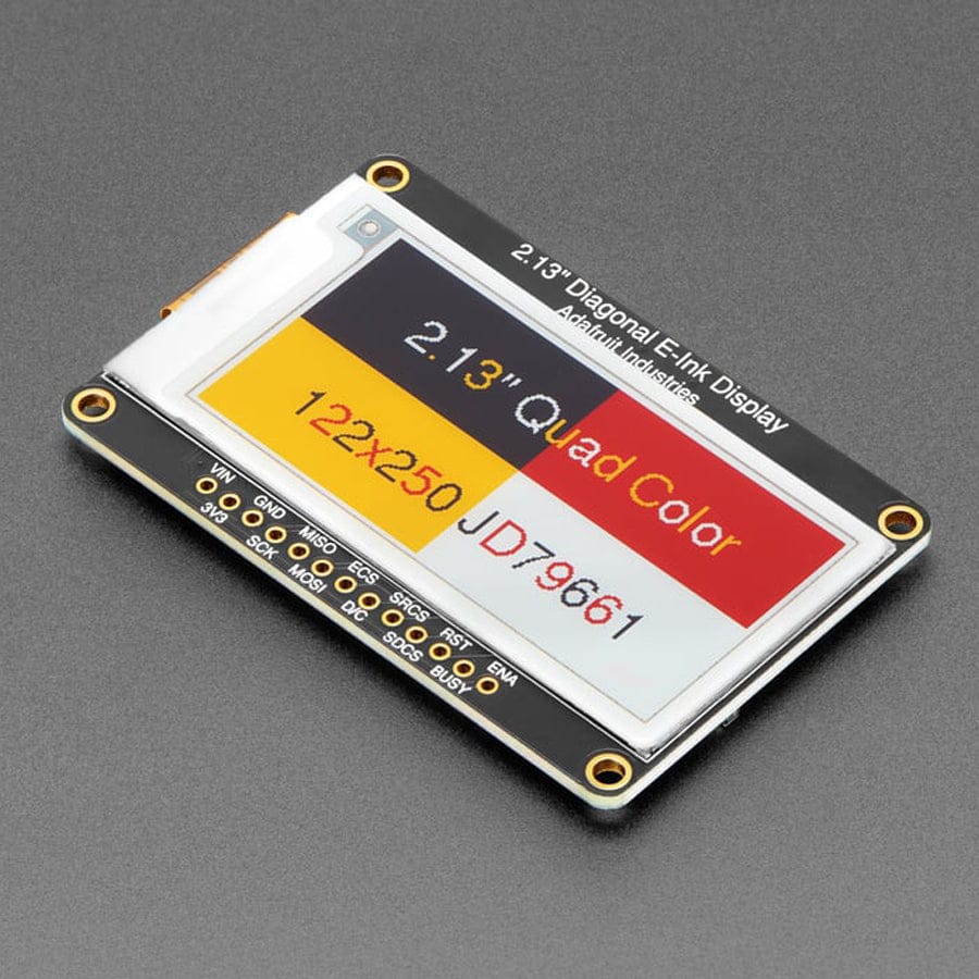
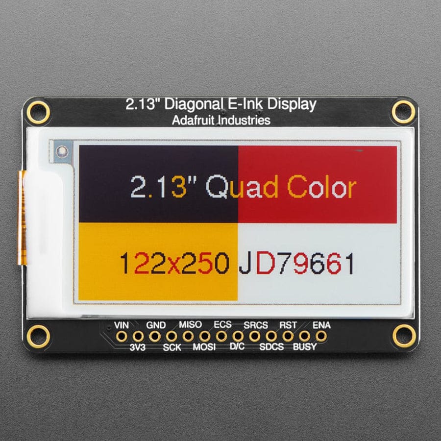
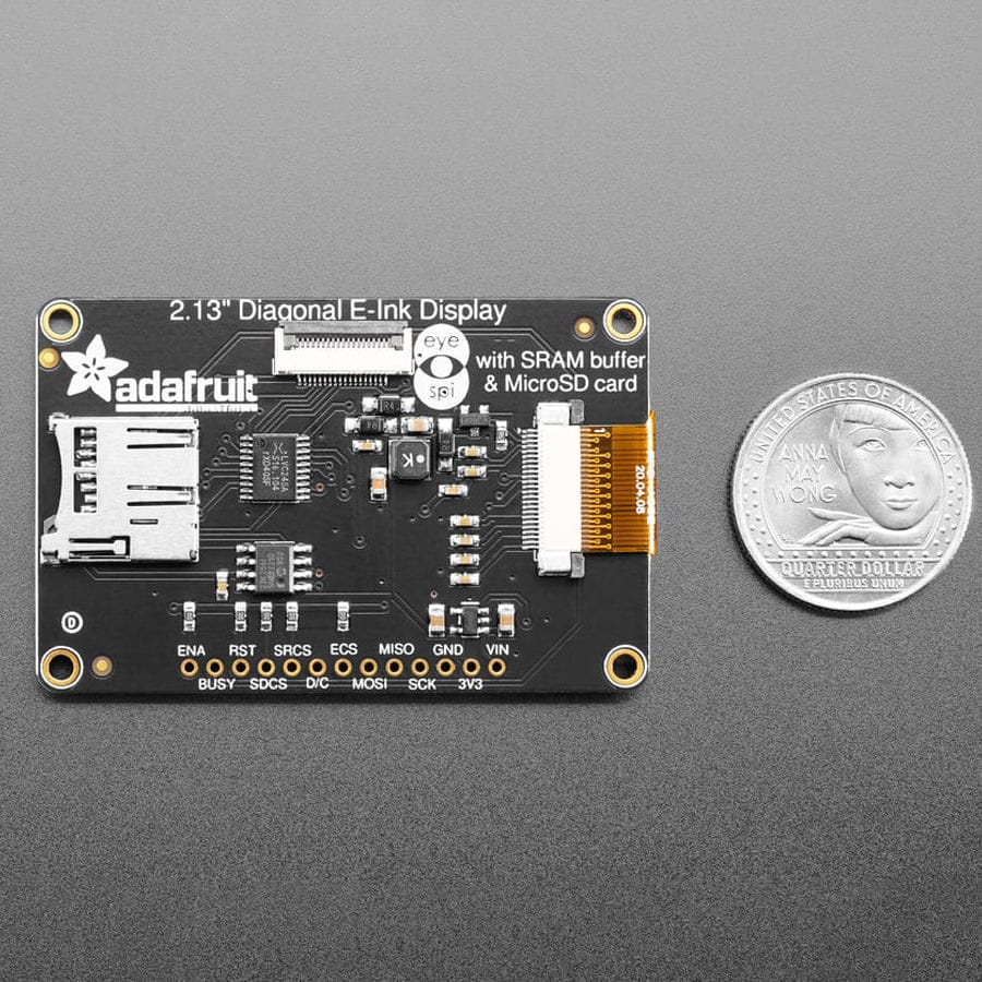
This breakout uses a 2.13" quad-colour display with 250 × 122 resolution, supporting red, black, yellow and white. It’s driven by the JD79661 chipset, so you’ll need firmware that supports it. Our Arduino and CircuitPython libraries handle that for you, letting you draw to the display just like an Adafruit_GFX screen.
One of the big challenges with ePaper is memory. A full frame buffer for this display takes about 7.5 KB, which is a lot for smaller microcontrollers. To avoid wasting RAM, we added a dedicated SRAM chip on the back of the board. It shares the same SPI bus as the display and only needs one extra pin. You can build your display content in SRAM and push it to the screen when you’re ready — no large frame buffer needed, and the library takes care of all the details.
We also included a microSD card slot, so you can store images, fonts or text files directly on the board. Everything is 3.3V and 5V logic safe, making it compatible with just about any microcontroller.
For ultra-low-power projects, the onboard 3.3V regulator has its enable pin broken out, allowing you to completely shut down the display, SRAM and microSD card when they’re not in use.
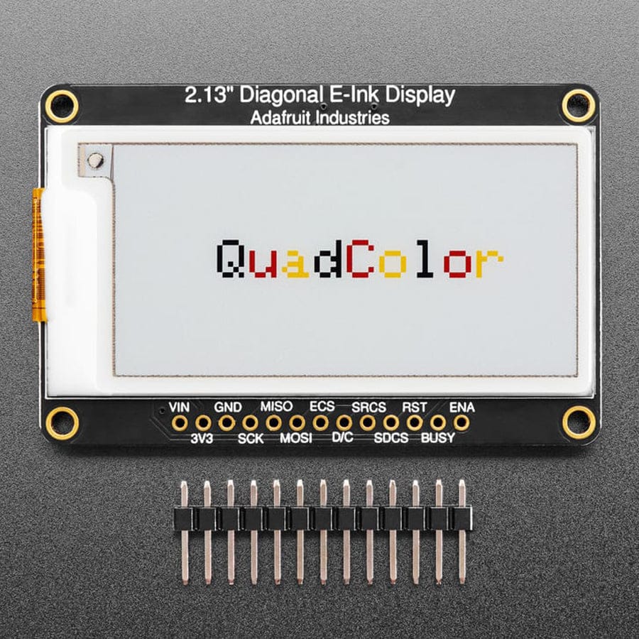
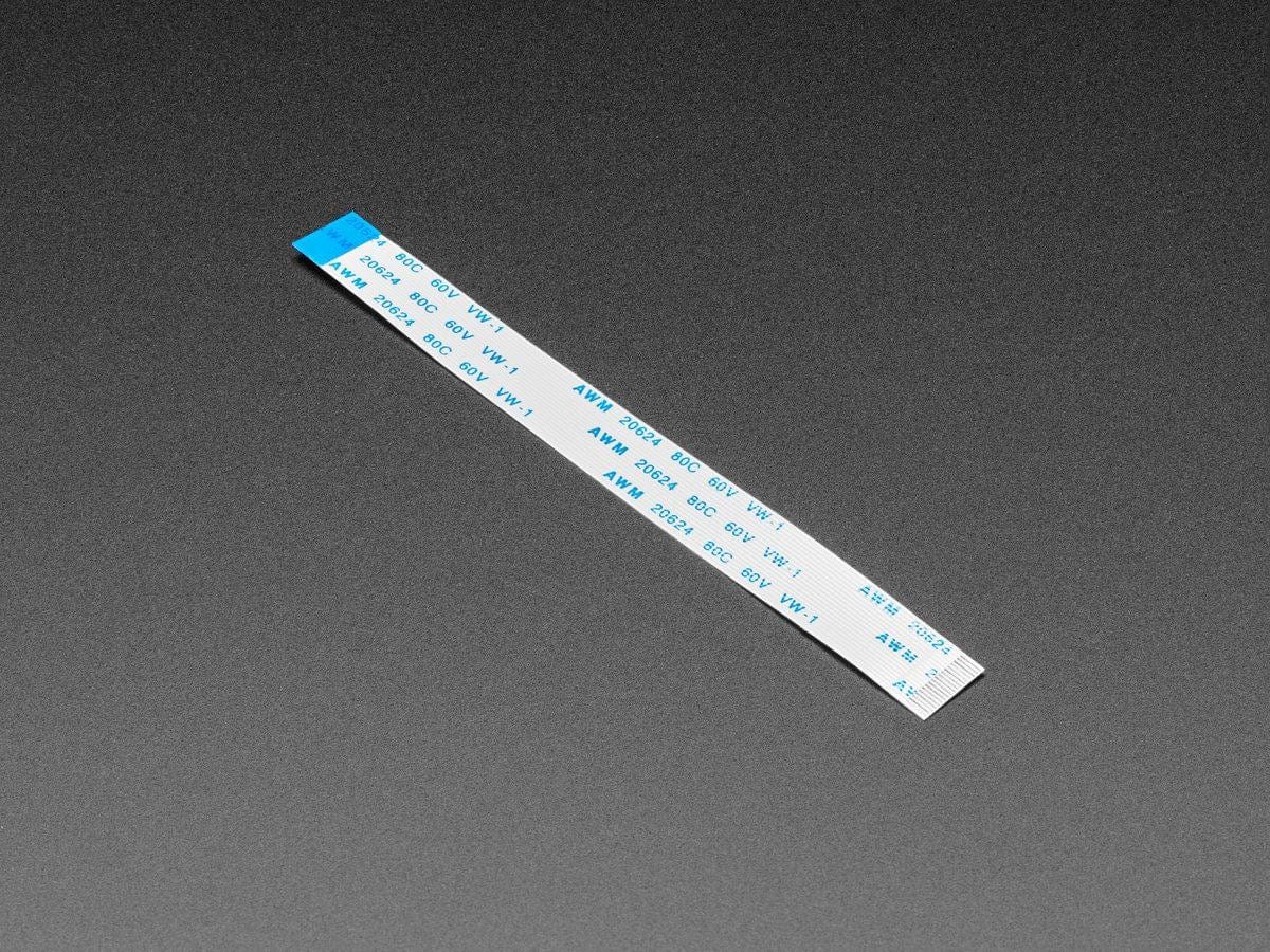
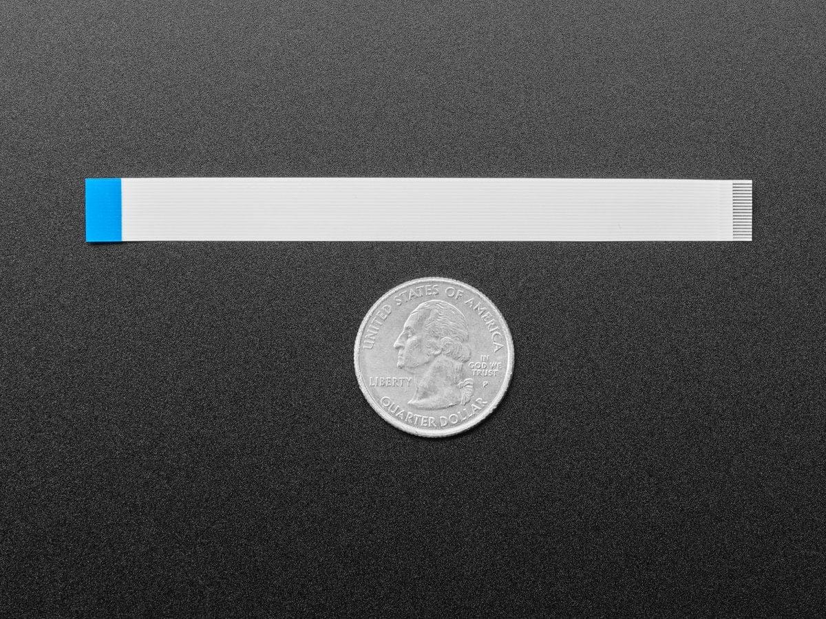
The breakout features an 18-pin “EYE SPI” standard 0.5 mm FPC connector with a flip-top latch. This lets you connect all GPIO pins using an FPC cable if you want to skip soldering entirely. The board comes fully assembled and tested, with headers included — you’ll just need to solder them on if you plan to breadboard it or mount it in a project.
Your payment information is processed securely. We do not store credit card details nor have access to your credit card information.