Adafruit PiCowbell CAN Bus for Pico - MCP2515 CAN Controller

AdafruitSKU: ADA5728
Price:
Sale price £9.60 Regular price £12
incl. VAT
excl. VAT
Save 20%
Stock:
Only 11 units left
Quantity:

Compatible with:

Awesome Extras

Save 20%
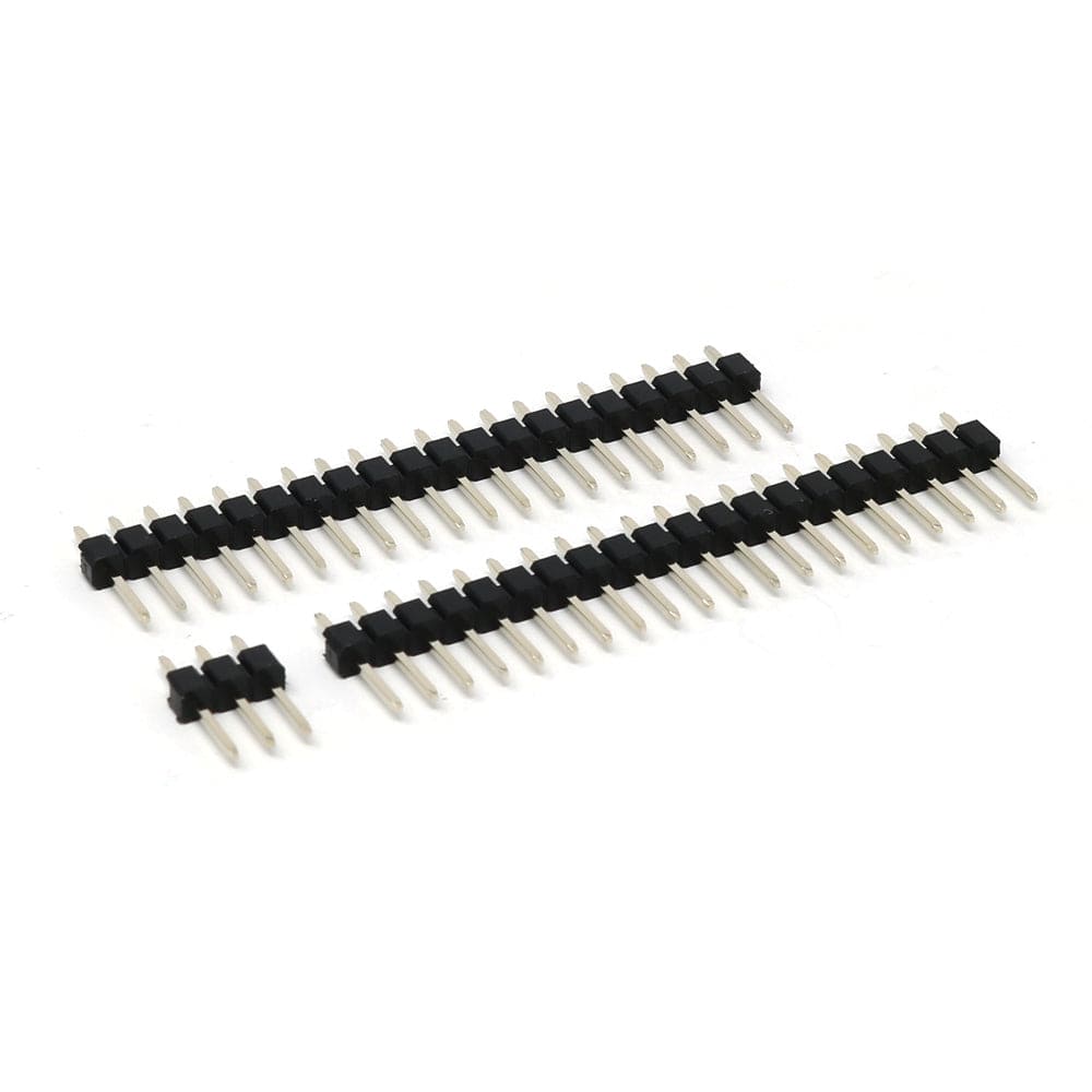
Male Header Set for Raspberry Pi Pico - The Pi HutMale Header Set for Raspberry Pi Pico - The Pi Hut
The Pi HutMale Header Set for Raspberry Pi Pico
Sale price £0.80 Regular price £1 incl. VAT excl. VAT
Save 10%
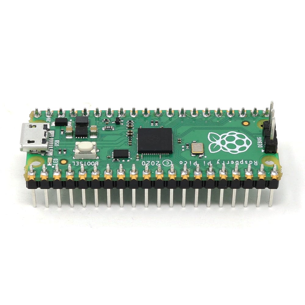
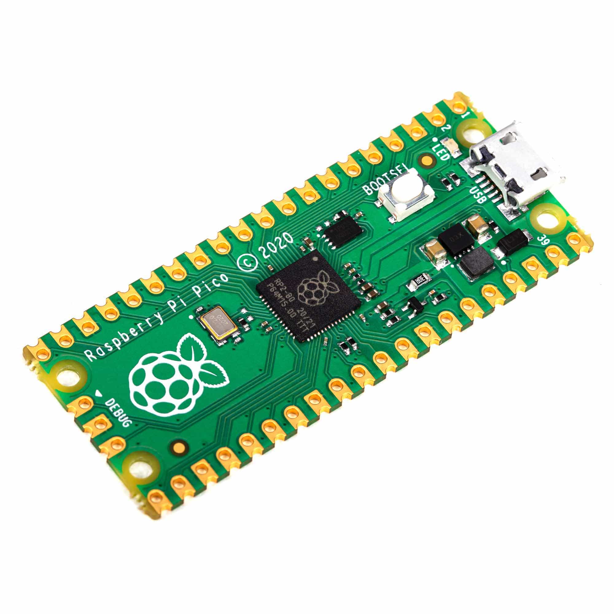
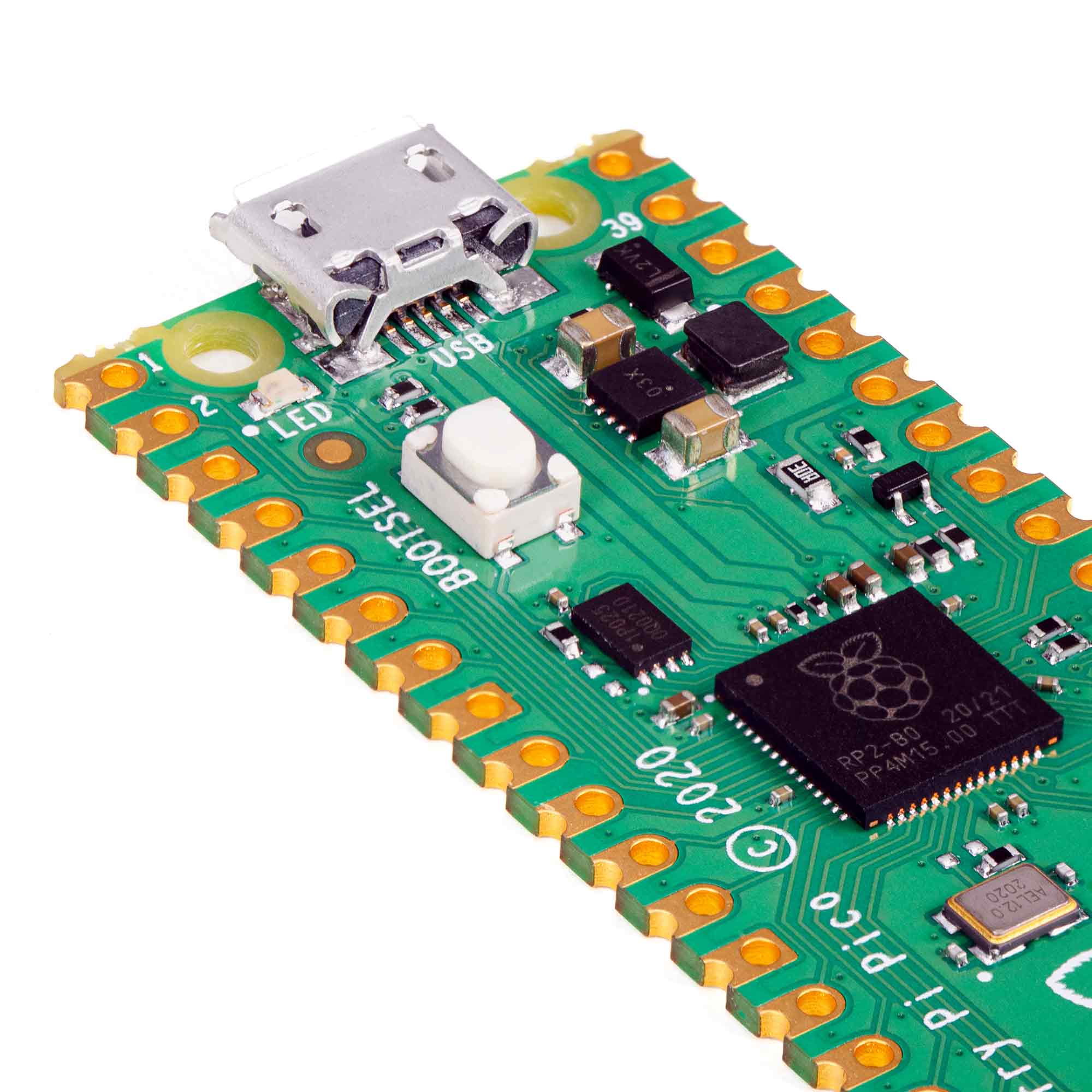
Raspberry Pi Pico - The Pi HutRaspberry Pi Pico - The Pi Hut
Raspberry PiRaspberry Pi Pico
Sale priceFrom £3.42 Regular price £3.80 incl. VAT excl. VAT
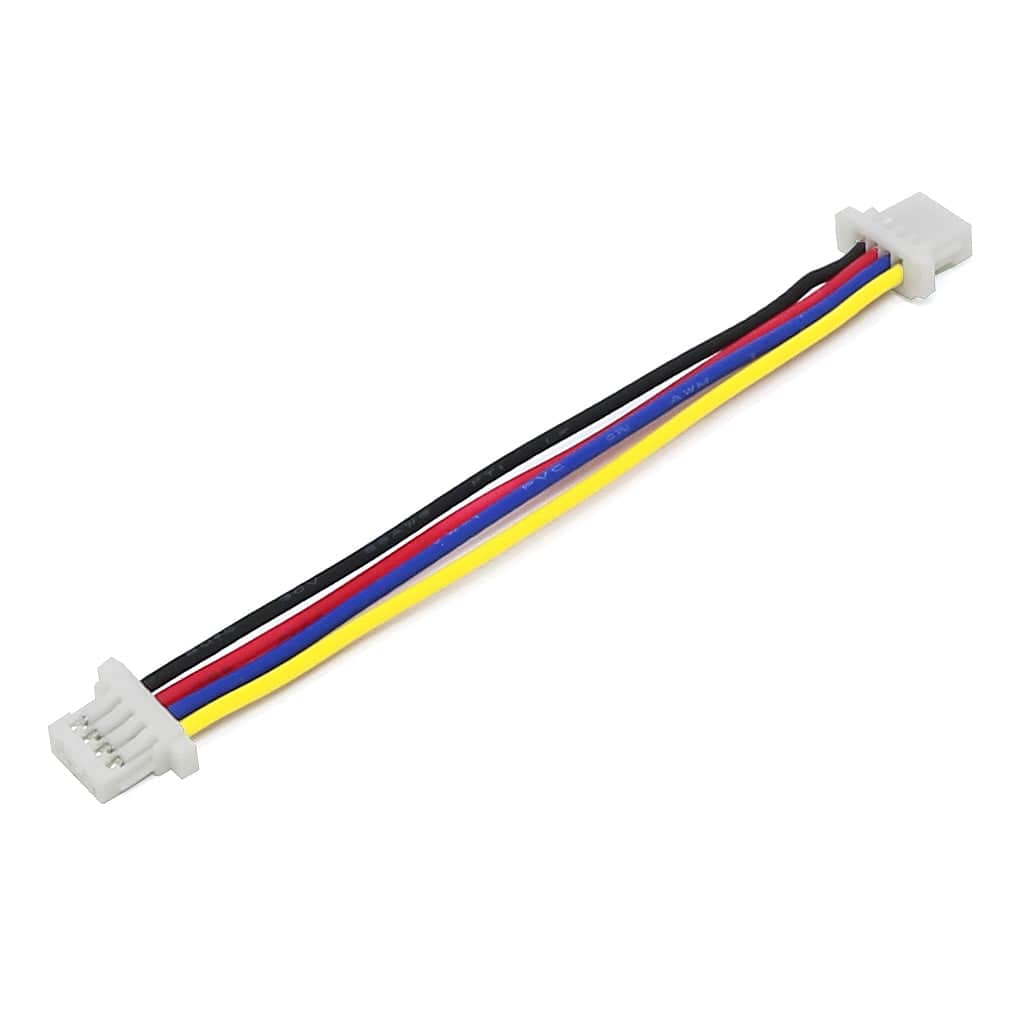
STEMMA QT / Qwiic Compatible JST-SH 4-Pin Cable (50mm) - The Pi HutSTEMMA QT / Qwiic Compatible JST-SH 4-Pin Cable (50mm) - The Pi Hut

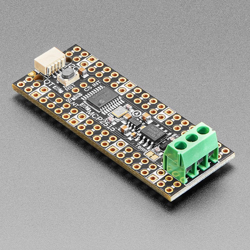
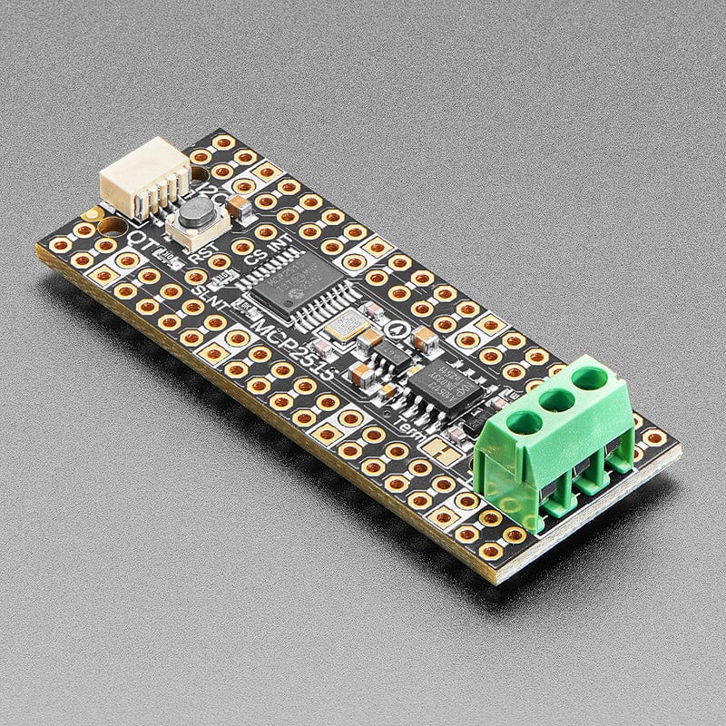
Ding dong! Hear that? It's the PiCowbell ringing, letting you know that the new Adafruit PiCowbell CAN Bus is in stock and ready to assist your Raspberry Pi Pico and Pico W project connect to CAN bus networks for automotive or robotics projects.

CAN Bus is a small-scale networking standard, originally designed for cars and, yes, busses, but is now used for many robotics or sensor networks that need better range and addressing than I2C and don't have the pins or computational ability to talk on Ethernet. CAN is 2 wire differential, which means it's good for long distances and noisy environments.

Messages are sent at about 1Mbps rate - you set the frequency for the bus and then all 'joiners' must match it, and have an address before the packet so that each node can listen in to messages just for it. New nodes can be attached easily because they just need to connect to the two data lines anywhere in the shared net. Each CAN device sends messages whenever it wants, and thanks to some clever data encoding, can detect if there's a message collision and retransmit later.

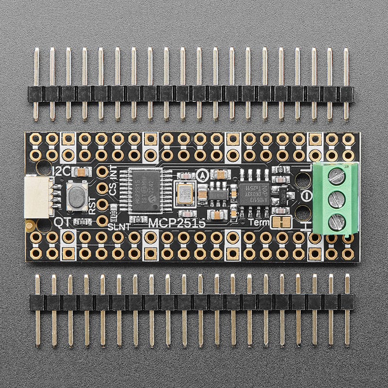
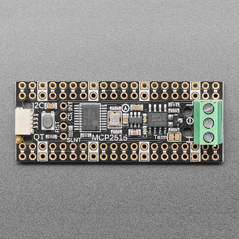
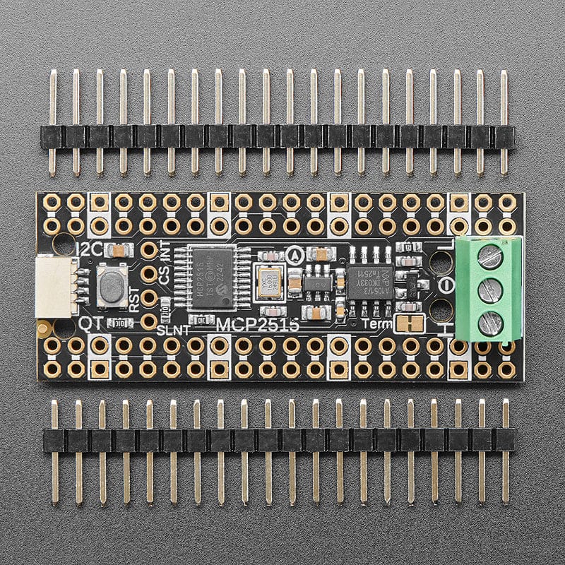
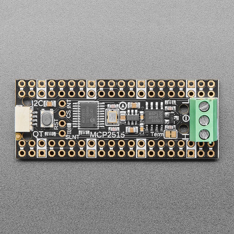
If you'd like to connect your Raspberry Pi Pico to a CAN Bus, the Adafruit PiCowbell CAN Bus has an MCP2515 controller and TJA1051/3 transceiver! The controller is the MCP2515, an extremely popular and well-supported chipset with drivers in Arduino and CircuitPython and only requires an SPI port and two pins for chip-select and IRQ. Use it to send and receive messages in either standard or extended format at up to 1 Mbps.

We've added a few nice extras to this PiCowBell to make it useful in many common CAN scenarios:

  • 5V charge-pump voltage generator, so even though you are running 3.3V on a Pico board, it will generate a nice clean 5V as required by the transceiver.
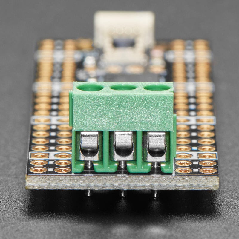
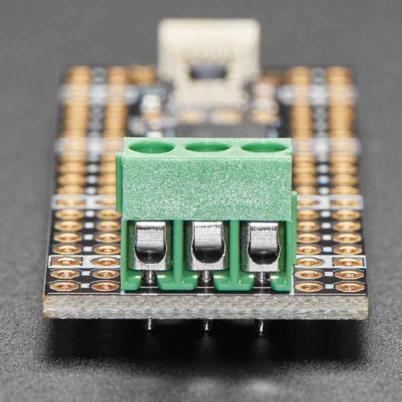
  • 3.5mm terminal block pre-soldered in to get quick access to the High and Low data lines as well as a ground pin.
  • 120-ohm termination resistor on board, you can remove the termination easily by cutting the jumper marked Term on the top of the board.
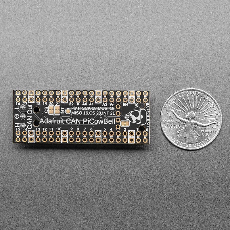
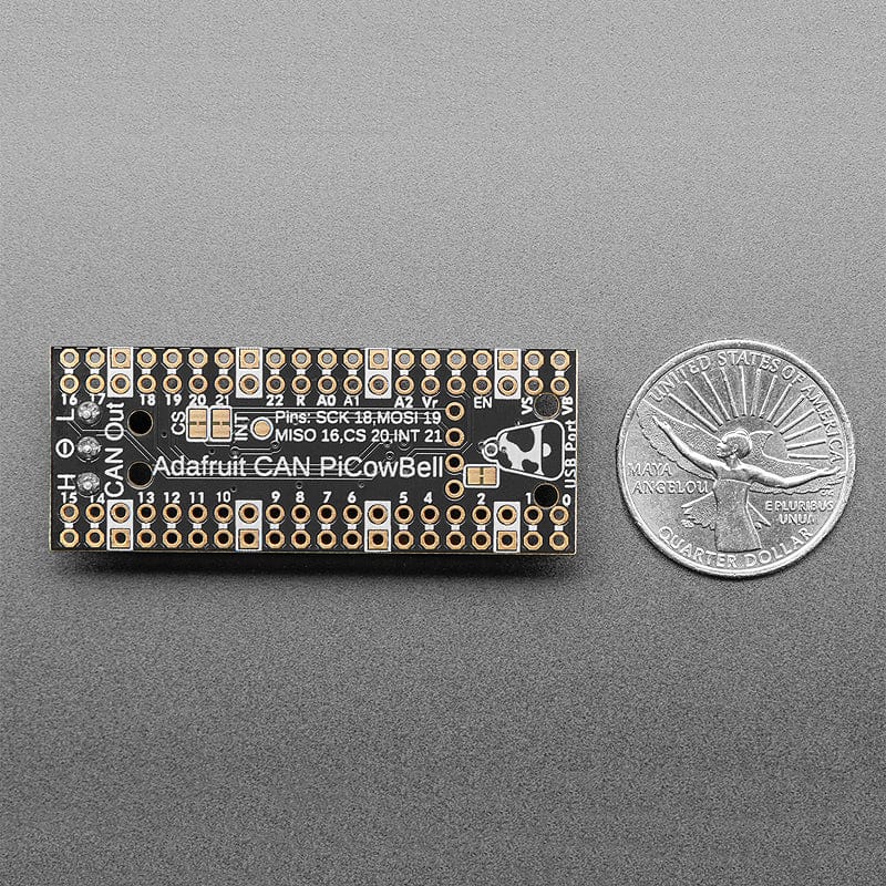
  • Pre-connected CS and INT pins on Pico GPIO #20 and #21. You can cut the bottom solder jumpers and use the breakout pads to connect to any two IO pins you like

Each order comes with an assembled PCB and header. You will need to solder in the header yourself, but it's a quick task.

Please Note! There are a lot of possible configurations, and we stock various headers depending on how you want to solder and attach them. Especially if you want the Pico on top so that the BOOTSEL button and LED are accessible.

  1. Use the Pico Stacking Headers if you want to be able to plug into a breadboard or other accessory with sockets.
  2. Use the Pico Socket Headers if you want to plug directly in and have a nice solid connection that doesn't have any poking-out bits.
  3. Use the Short Socket Headers for a very slim but pluggable design; note that you'll want to trim down the Pico's headers or use the short plug headers on the Pico to have a skinny sandwich.
  4. Solder the PCB directly to the Pico headers - of course, this is very compact and inexpensive, but you won't be able to remove the PiCowbell.

The PiCowbell CAN Bus provides you with:

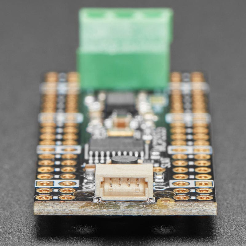
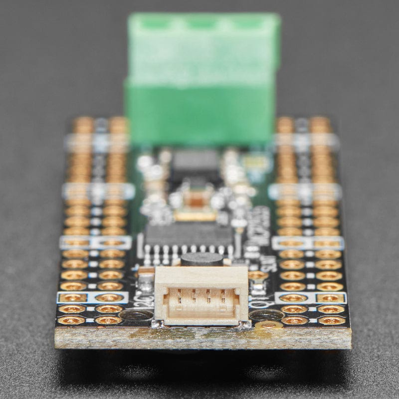
  • Right angle JST SH connector for I2C / Stemma QT / Qwiic connection. Provides 3V, GND, IO4 (SDA), and IO5 (SCL)
  • Reset button - Press to restart your program
  • Every pad on the 'bell has a duplicate hole pad next to them for solder-jumpering
  • The ground pads have white silkscreen rectangles to easily identify, plus one long ground strip near the reset button
  • Gold-plated pads for easy soldering

If using the Philhower Arduino core, the Wire peripheral is already set up to use IO4 and IO5, and SPI defaults on IO16, IO18 and IO19. If using CircuitPython or MicroPython, you'll need to let the code know to look at 4+5 for SDA+SCL pins and configure the SPI port for SCK=18, MOSI=19 and MISO=16.

Specifications

  • Bitrate Max [MBits/s] - 1
  • CAN Controllers - 1
  • Internal CAN Clock - No
  • LPM Current Max [uA] - 0
  • Message RAM [KB] - 0
  • Operating Voltage Min. [V] - 2.7
  • Operating Voltage Max. [V] - 5.5
  • Rx Buffers - 2
  • SPI Interface - Yes
  • Serial Bus Speed [MHz] - 10
  • Standby Current Max [uA] - 0
  • Operating Temperature Min. [°C] -40
  • Operating Temperature Max. [°C] - 125
  • Time Stamp (Bits) - 0
  • TX Buffers - 3
  • TX Event FIFO - 0
  • TX Queue - 0
  • CAN FD - No
  • Product Dimensions: 52.0mm x 20.2mm x 10.0mm
  • Product Weight: 5.1g

Resources

Payment & Accreditations

Payment methods
Visa Mastercard Maestro PayPal Amazon Klarna

Your payment information is processed securely. We do not store credit card details nor have access to your credit card information.

Accreditations