Adafruit 12-Channel 16-bit PWM LED Driver - SPI Interface (TLC59711)
Price:
Sale price
£7.20
Stock:
Quantity:
 Skip to content
Cart
Your cart is empty


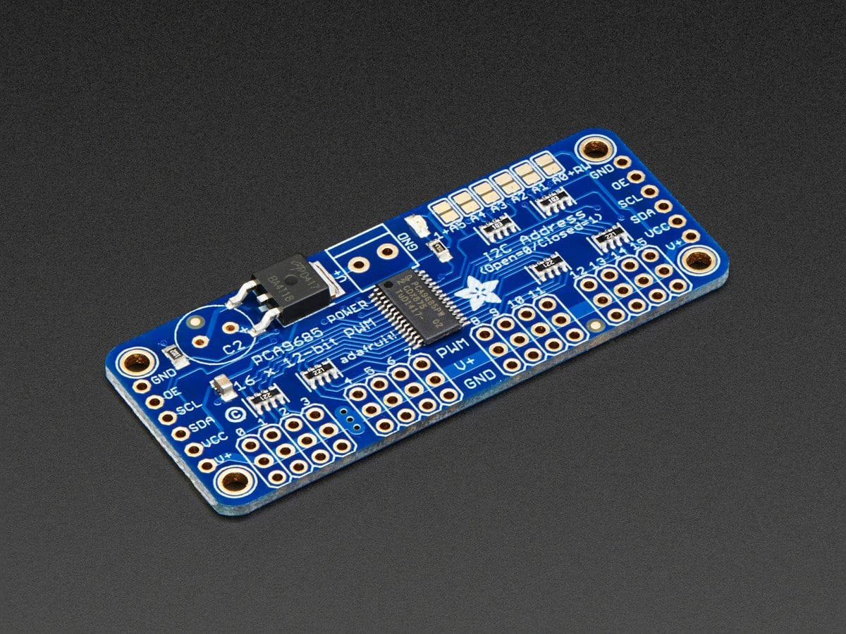
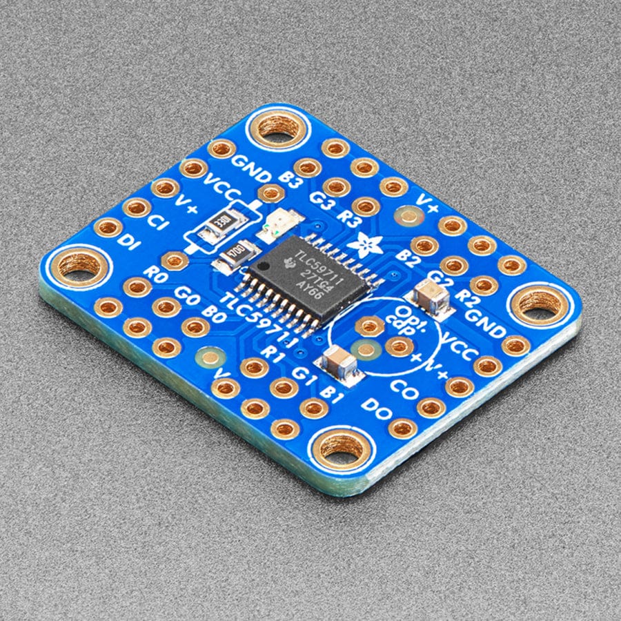
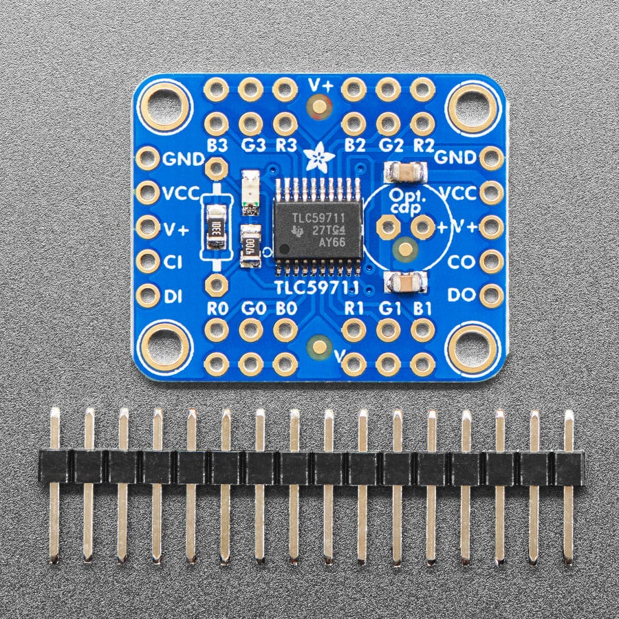
For all of you out there who want to control 12 channels of PWM, we salute you! We also would like you to check out this breakout board for the TLC59711 PWM driver chip. This chip can control 12 separate channels of 16-bit PWM output. This is the highest-resolution PWM board we've seen! Designed (and ideal) for precision LED control, this board is not good for driving servos. If you need to drive servos, we have a controller for that over here.
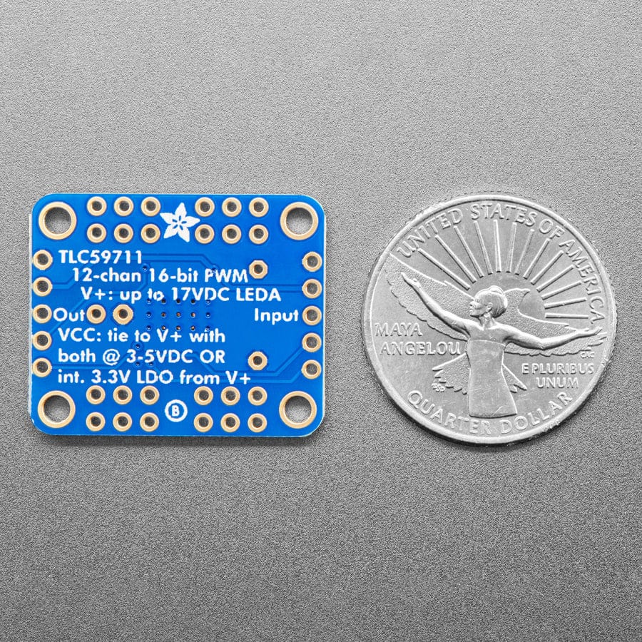
Only two "SPI" pins are required to send data (our Arduino library shows how to use any digital microcontroller pins). Best of all, the design is completely chainable. As long as there's enough power for all the boards you can chain as many as you'd like, like a little trail of blue PCBs stretching out into the sunset. Each of the 12 outputs a constant current and open drain. You can drive multiple LEDs in series, with a V+ anode supply of up to 17V. If you want to drive something that requires a digital input, you must use a pullup resistor from the drive pin to your logic level to create the full waveform.
One resistor is used to set the current for each of the outputs, the constant current means that the LED brightness doesn't vary if the power supply dips. We use a 3.3K resistor for about 15mA but you can solder a thru-hole resistor over it if you'd like to change that value. Check the TLC59711 datasheet for details on resistor-to-current values. There's also a handy on-chip 3.3V regulator which you can use if you need a logic level regulator.
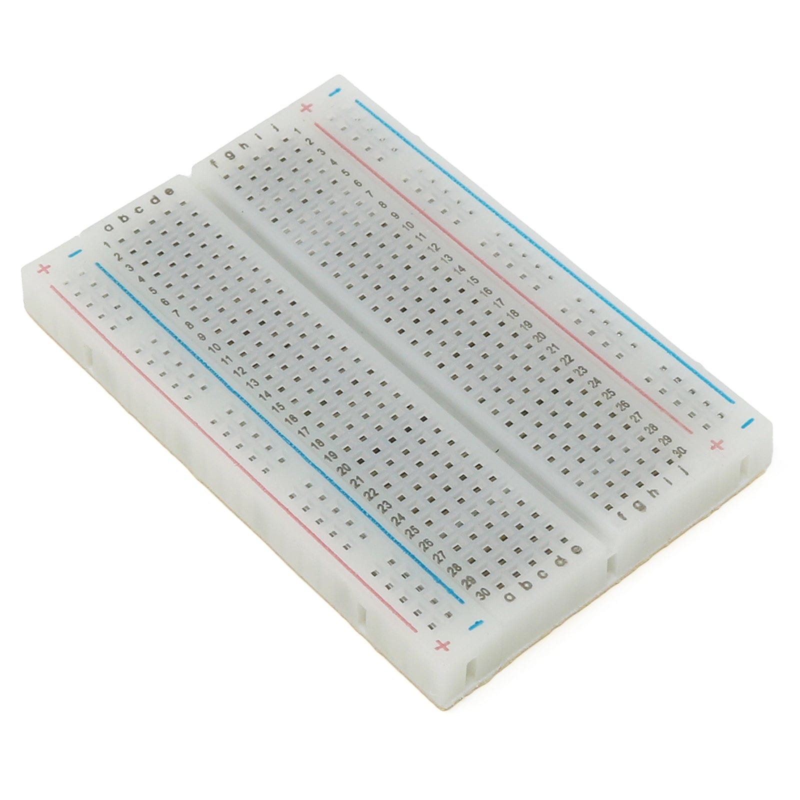
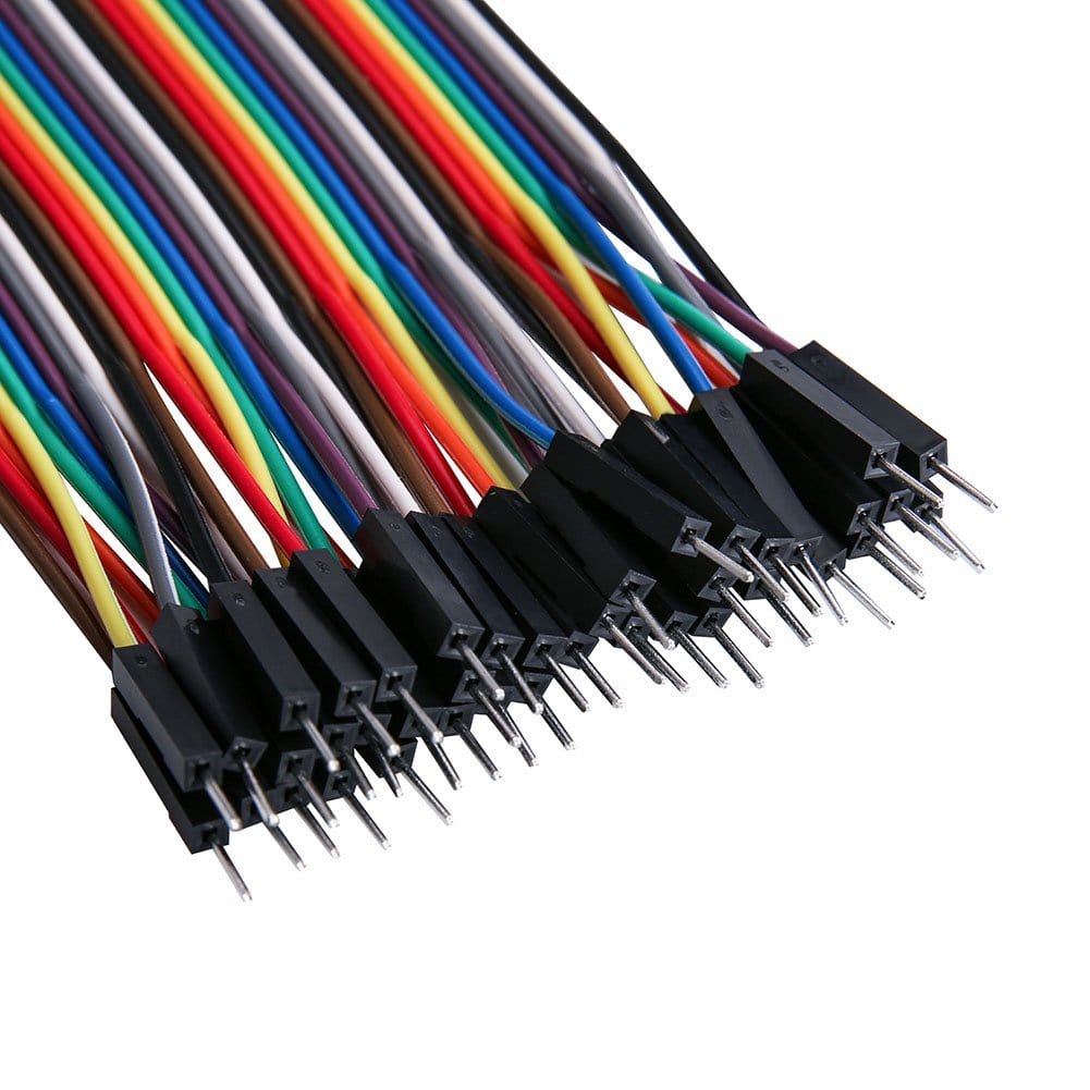
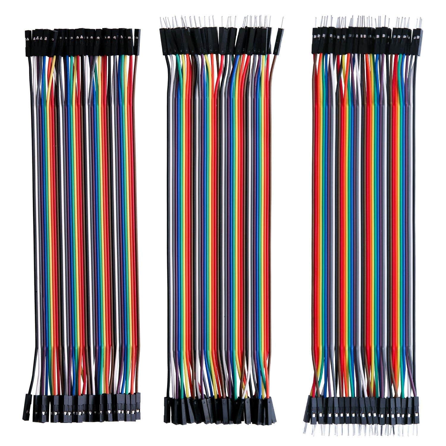
We include a few extras to make this board easy to use: a green power-good LED, four mounting holes and a current-set resistor. A bit of 0.1" header is also included so you can solder it on and plug it into a breadboard.
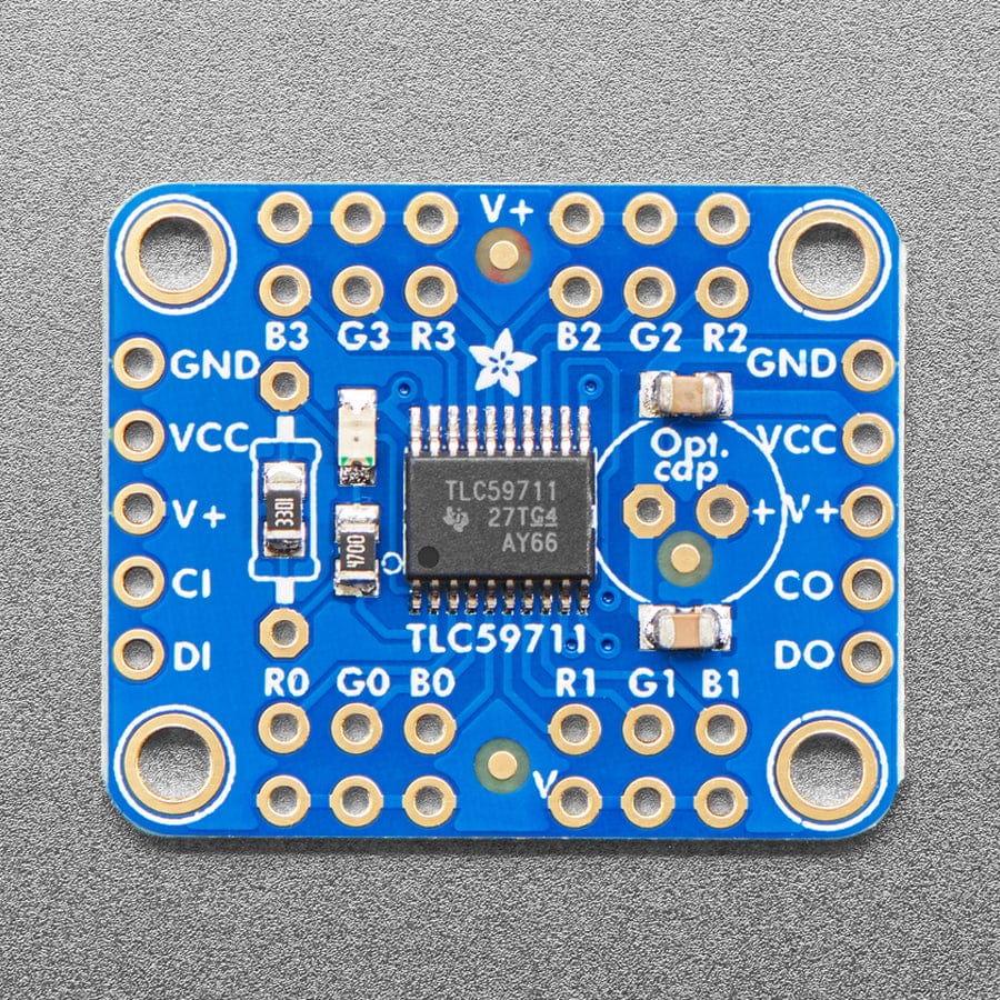
To use: Power V+ with 5-17VDC, and connect ground to the common ground. Then send 3-5V logic SPI data on DIN (data in) and CLK (clock). Our Arduino library will get you started with blinking LEDs, install it and run the example code with the noted pin configuration.
There's a typo in the silkscreen, the second R0 should be R1 - but you knew that already!
As of July 31st, 2024 – We've updated this PCB with Adafruit Pinguin to make a lovely and legible silkscreen.
Your payment information is processed securely. We do not store credit card details nor have access to your credit card information.
New content loaded
Login / Signup