
Raspberry Pi 7" Touch Screen Assembly Guide
Before we assemble the touch screen, we need to make sure that our Raspberry Pi has the latest version of Raspberry Pi OS, and that all the software is up to date.
Hook up your Pi to a monitor, plug in your keyboard and mouse and boot your Pi into Raspberry Pi OS. Once booted up, open a new Terminal window and type the following commands, hitting enter after each one:
sudo apt-get update
sudo apt full-upgrade
After we have updated the Pi, safely shut it down, unplug everything and put it to one side.
Building the touch screen
As we will be working on the back of the screen, and the screen will be facing a table, we recommend you leave the protective film on until assembly is complete. It's also wise to place the screen on something soft and clean like a microfibre cloth.
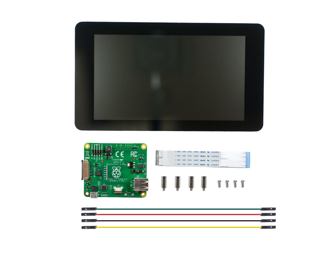
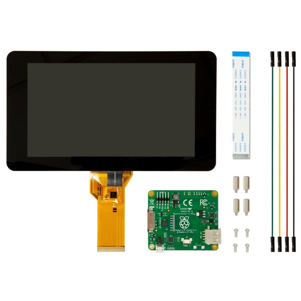
Here is everything that you should have, out of the box:

Start by connecting the large ribbon cable from the screen to the connector on the underside of the controller board. You will need to carefully undo the clamp before inserting the cable. Make sure to press the clamp in to secure the ribbon in place.
Note: this is sometimes already connected depending on our current supplier.
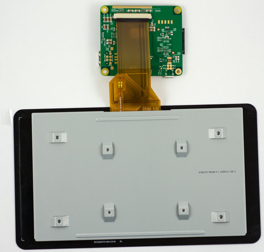
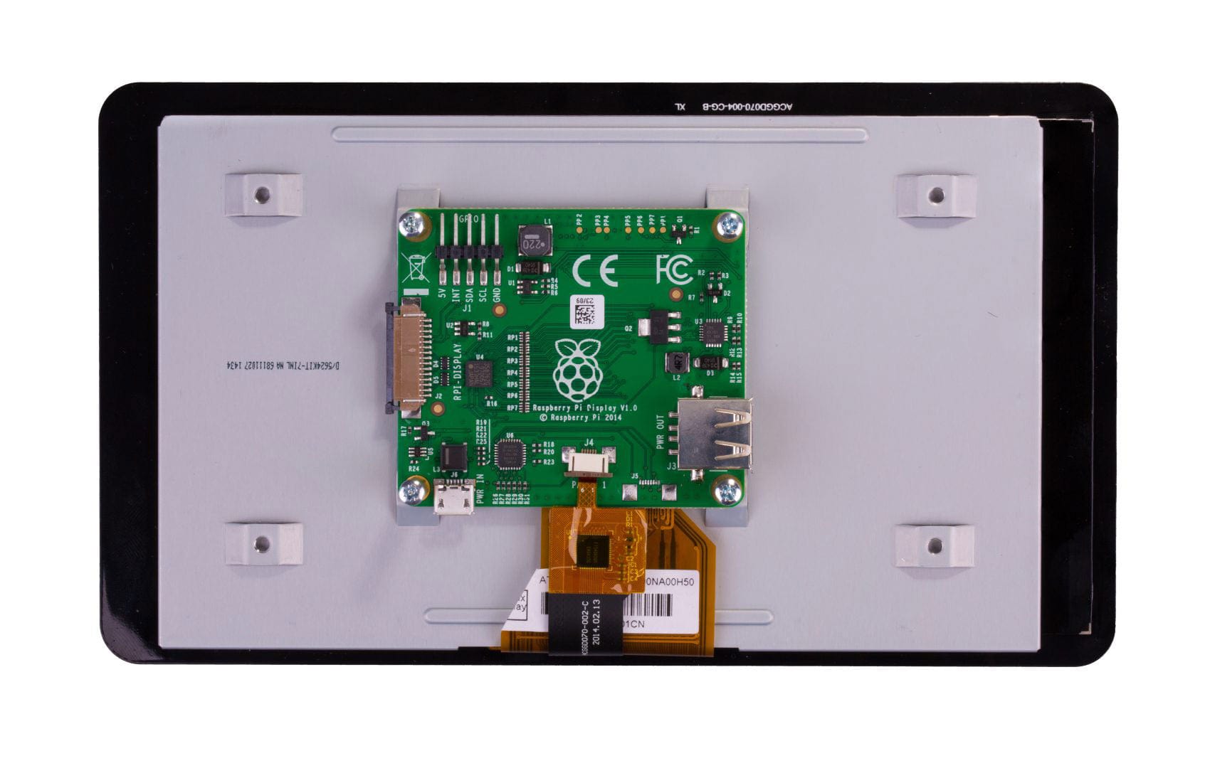
Now turn the controller board over, and connect the small ribbon cable from the screen to the board. Same principle as above, undo the clamp, insert cable, press clamp closed to secure ribbon in place.


Using the 4 standoffs provided, secure the controller board to the screen


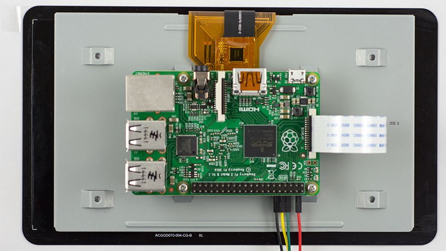
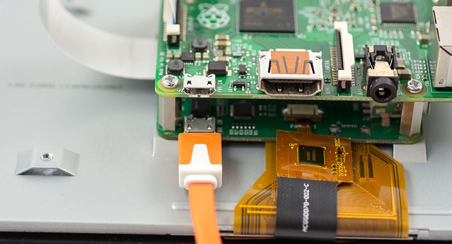
Using the white ribbon cable supplied, connect one end to the controller board, making sure that this end has the blue tab facing down, towards the board (the opposite end, the end not being attached to the controller board, should have the blue tab facing up, so you can see it):


Now connect only the Red and Black jumper wires, that were supplied to the controller board.
- Red – 5V
- Black – GND
You will see green and yellow wires in the images below - these are no longer required.


Mount the Raspberry Pi on top of the 4 standoffs:

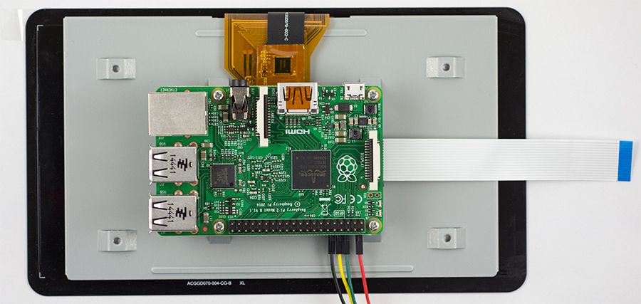
Connect the white ribbon to the Raspberry Pi’s Display port

Now connect the jumper wires to the Pi. Again, only the black and red wires are required.
- Red – Pin 2
- Black – Pin 6


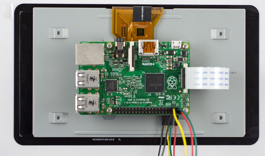
Now it’s time to power it all. Plug an official Raspberry Pi power supply into the controller board (the controller board will power your Pi via the jumper wires) and away you go!).

18 comments
The Pi Hut
@Lazlo – They should just unscrew from the thread in the rear panel – standard directions i.e. lefty loosy, righty tighty.
@Lazlo – They should just unscrew from the thread in the rear panel – standard directions i.e. lefty loosy, righty tighty.
Lazlo
the screen came with the standoffs on out of the box – how would i go about taking them off?
the screen came with the standoffs on out of the box – how would i go about taking them off?
William Lewsey
No matter which Pi I try it with, the display does nothing. Not even a flicker . I’ve updated the software on the Pi’s but still nothing, any ideas?
No matter which Pi I try it with, the display does nothing. Not even a flicker . I’ve updated the software on the Pi’s but still nothing, any ideas?
The Pi Hut
@yuval The yellow and green cables are no longer required (but they still include them with the display).
@yuval The yellow and green cables are no longer required (but they still include them with the display).
The Pi Hut
@Anthony McDonald
@JM
Try powering the Pi via Micro-USB, then feeding the display with 5V/GND cables (opposite to what this article states)
@Anthony McDonald
@JM
Try powering the Pi via Micro-USB, then feeding the display with 5V/GND cables (opposite to what this article states)
yuval
i have RPI3 and a 7" toch screen.
in raspberry pi offical website, they write only the red(5V) and the black(GND) wires are required so what the yellow(GPIO3) and the green(GPIO2) needed ? what they do ?
i have RPI3 and a 7" toch screen.
in raspberry pi offical website, they write only the red(5V) and the black(GND) wires are required so what the yellow(GPIO3) and the green(GPIO2) needed ? what they do ?
ps3460
I have a Pi5 with AI HAT.
Can I still use this screen, or do I need to go for HDMI?
I have a Pi5 with AI HAT.
Can I still use this screen, or do I need to go for HDMI?
Anthony McDonald
“I’m using this with a pi3b+ and a brand new official psu, but getting undervoltage warnings. What are the current requirements of the display and driver board please?”
Me too!
“I’m using this with a pi3b+ and a brand new official psu, but getting undervoltage warnings. What are the current requirements of the display and driver board please?”
Me too!
JM
I’m using this with a pi3b+ and a brand new official psu, but getting undervoltage warnings. What are the current requirements of the display and driver board please?
I’m using this with a pi3b+ and a brand new official psu, but getting undervoltage warnings. What are the current requirements of the display and driver board please?
I Dont like saying my name
Is this easy to set up? I’m thinking about getting a pi and I dont want to spend ages setting it up.
Is this easy to set up? I’m thinking about getting a pi and I dont want to spend ages setting it up.
The Pi Hut
@Daniel – If you take a look at our Raspberry Pi 5 page, you’ll see that a special adapter cable is required to use the display with the smaller ports on the board: https://thepihut.com/products/display-adapter-cable-for-raspberry-pi-5
@Daniel – If you take a look at our Raspberry Pi 5 page, you’ll see that a special adapter cable is required to use the display with the smaller ports on the board: https://thepihut.com/products/display-adapter-cable-for-raspberry-pi-5
Daniel
Is this definitely compatible with the Pi 5? I have one in my hands and it appears the ribbon connector on the Pi 5 is smaller than the ribbon provided, making the screen incompatible.
The ribbon in the traditional display ribbon slot is now a tiny one for PCI+, so the CAN/DISP 0/1 ribbons are the next logical choice, but those aren’t big enough. Thanks!
The Pi Hut
@Andrei – No, the official display is DSi only. You may want to check out our HDMI display section for a HDMI alternative: https://thepihut.com/collections/hdmi-displays-for-raspberry-pi
@Andrei – No, the official display is DSi only. You may want to check out our HDMI display section for a HDMI alternative: https://thepihut.com/collections/hdmi-displays-for-raspberry-pi
Andrei
Hi there,
Can the display be connected to the PI ModelB with HDMI cable (no dsi), please?
Hi there,
Can the display be connected to the PI ModelB with HDMI cable (no dsi), please?
MHS
I have an old 7 inch touch screen which has lost touch sensitivity in the corner normally occupied
by the menu button. I assume the screen is capacitive and should not suffer wear problems associated
with resistive touch systems. Is there any history of similar problems and could it get worse?
Most of the screen area works as expected and I have moved the menu to a good area.
Thomas McIntyre
Where can i get a replacement connector for J4, the one on my control board is broke and has separated from the board or is it possible to send the board off to be repaired?
Where can i get a replacement connector for J4, the one on my control board is broke and has separated from the board or is it possible to send the board off to be repaired?
The Pi Hut
@Brandon – It doesn’t use any of the GPIO pins from the header, so you’ll still have all of them to play with.
@Brandon – It doesn’t use any of the GPIO pins from the header, so you’ll still have all of them to play with.
Brandon
This may be a silly question, but does the ribbon cable connected to the DSI port on the PI use any of the Pi’s GPIO pins internally? Most screens provide a list of unused pins that can be used for other purposes, but I can’t find a similar list for this screen. Does this mean that all of the GPIO pins are available?
This may be a silly question, but does the ribbon cable connected to the DSI port on the PI use any of the Pi’s GPIO pins internally? Most screens provide a list of unused pins that can be used for other purposes, but I can’t find a similar list for this screen. Does this mean that all of the GPIO pins are available?