An introduction to Raspberry Pi GPIO
What’s so special about Raspberry Pi?
It’s a question that I’m often asked and the answer is usually the same. The GPIO pins of course! Those little stabby pins along the top of the Pi that let you connect buttons, buzzers, sensors and HATs.
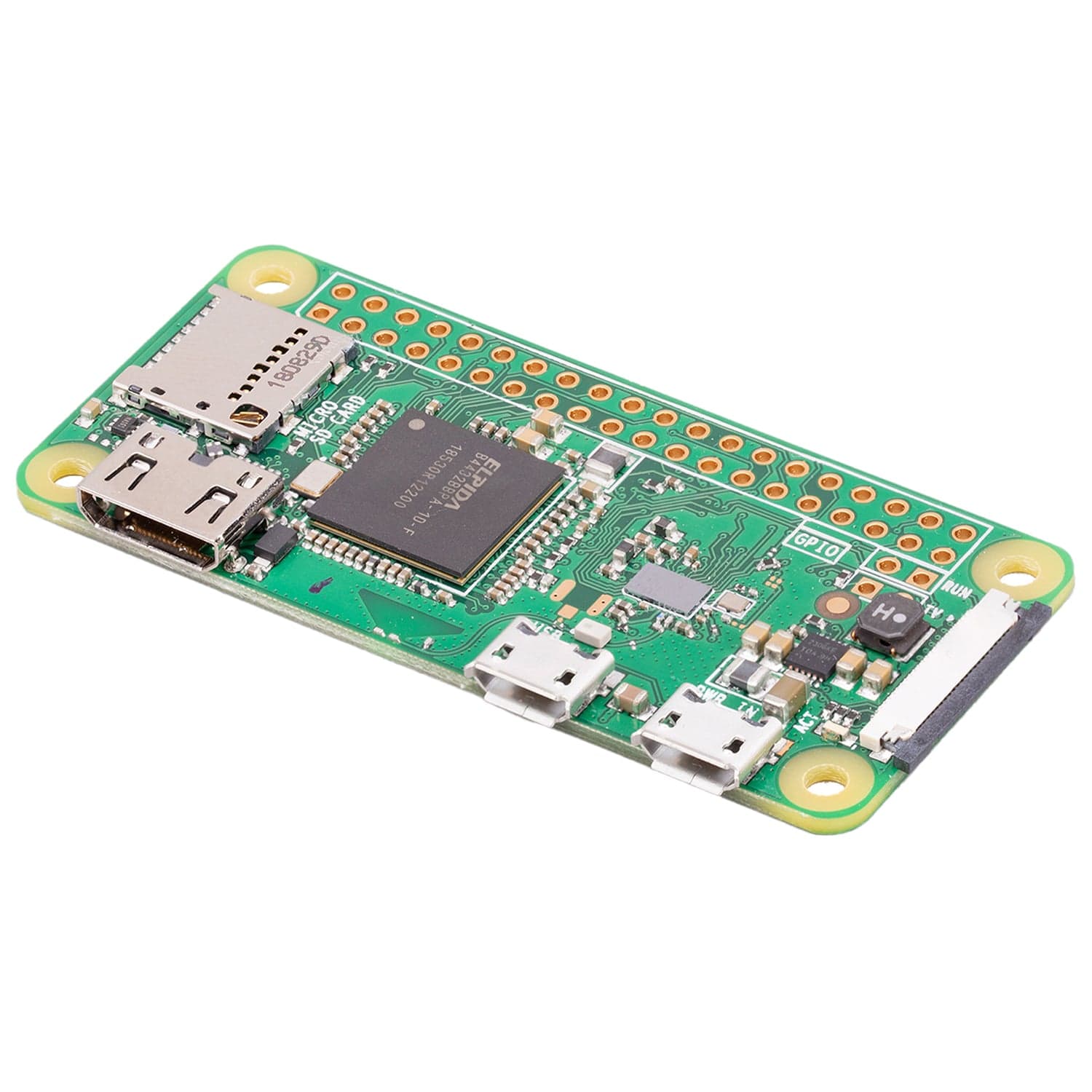
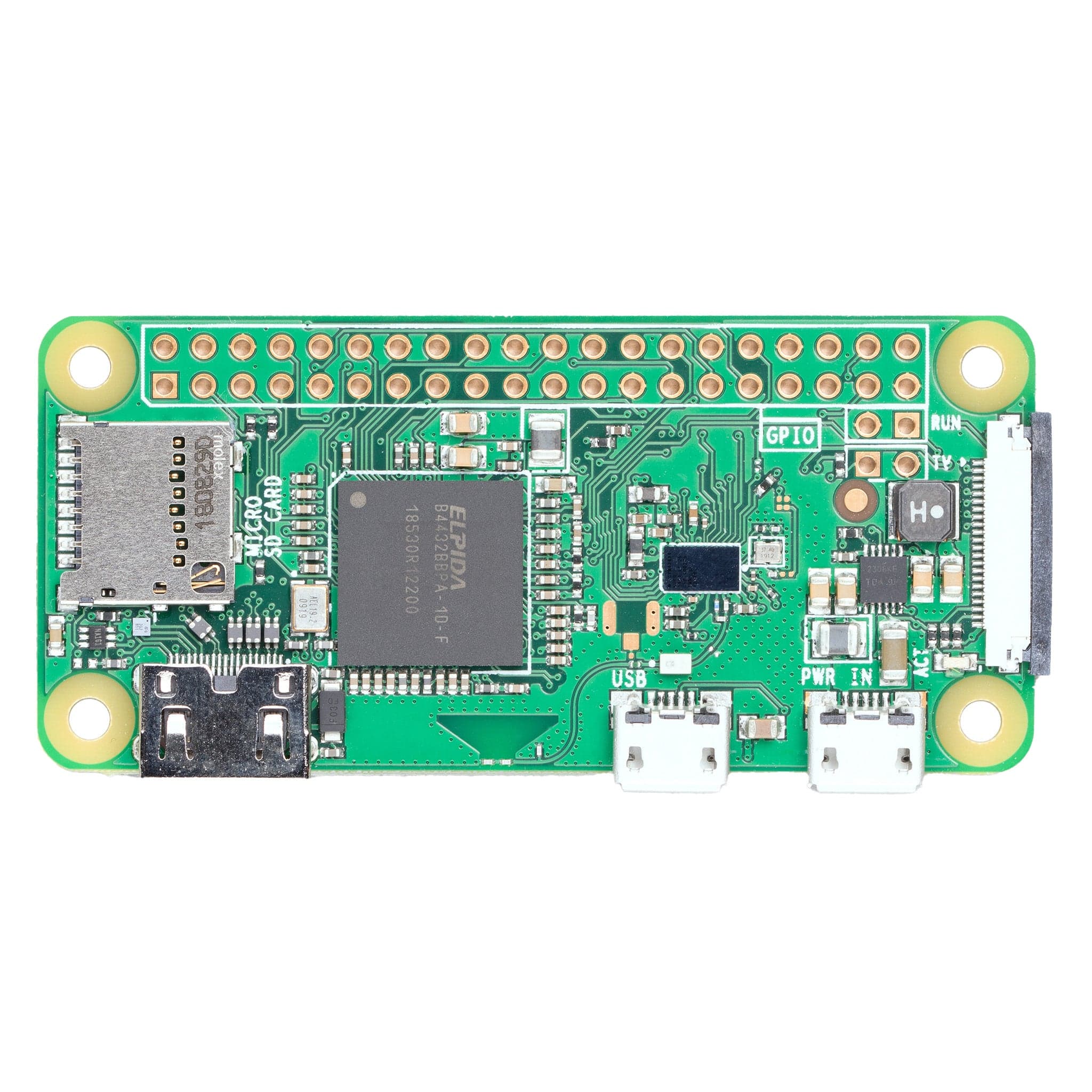
 On the first two models of Raspberry Pi, there were only 26 pins, but it quickly became apparent that more is better and so for every model since the B+ in July 2014, there have been 40 GPIO pins on the Raspberry Pi A and B models. On the Raspberry Pi Zero, there are still 40 pins that you can use, but they are ‘headerless’ meaning that you can either solder directly onto the board in place of the pins, or you can solder your own header on (which is not as tricky as it sounds, and can be great fun).
But what exactly makes those pins so special?
GPIO stands for General Purpose Input-Output, what this means in layman terms is that the the pins can be used as either inputs, which receive data, or outputs, which react to data. An input might include a button or a sensor, an output could be an LED or a buzzer. This means that we can create exciting physical computing projects which react and interact with the real world instead of just learning to program text on the screen!
Not all of the pins are programmable and controllable, in fact, there are only 26 that can be used in this way, but the other pins all serve valuable purposes too.
Take a look at this pin diagram created by the Raspberry Pi Foundation which tells you firstly, which pins are programmable GPIO pins, in yellow, but also highlights some information about the other pins too. This diagram assumes that pin 21 is the pin closest to the USB ports.

The first two pins in the top left are labelled as 5v, which means that if you’re using a component that needs power, you can connect it to the 5v power. Likewise, if your component needs less power, you can connect it to one of the two 3.3v pins - this can be a good way to test an LED, by connecting it straight to a 3.3v and a ground pin (via a resistor of course), you can check whether it works. The 3.3v should mean that your LED is ‘always on’, if it doesn’t turn on when tested this way, you may find that your LED no longer works.
There are eight pins which are labelled as ground pins. If you think back to primary school physics, you might recall that in order to complete any circuit, it needs to be attached to a negative, or ground. Basically, any circuit you make needs to have one side attached to a ground pin, however, it’s possible for components to share a common ground, for example if you use a breadboard, you could make an entire row or column ground and connect components to that rather than each part to an individual ground pin.
Finally, there are two pins labelled in the diagram as ID EEPROM, don’t worry, you don’t need to know about these two pins as they relate to HATs and add-on boards. The key thing to remember is that you shouldn’t be plugging things into them!
HATs?
One of the great things about Raspberry Pi is that there are so many companies innovating and creating exciting products that can be easily attached to it! One of the reasons that there are now 40 GPIO pins is to make it easier for companies to make HATs - those two EEPROM pins mean that HATs can easily be plugged in and integrate with the Raspberry Pi hardware!
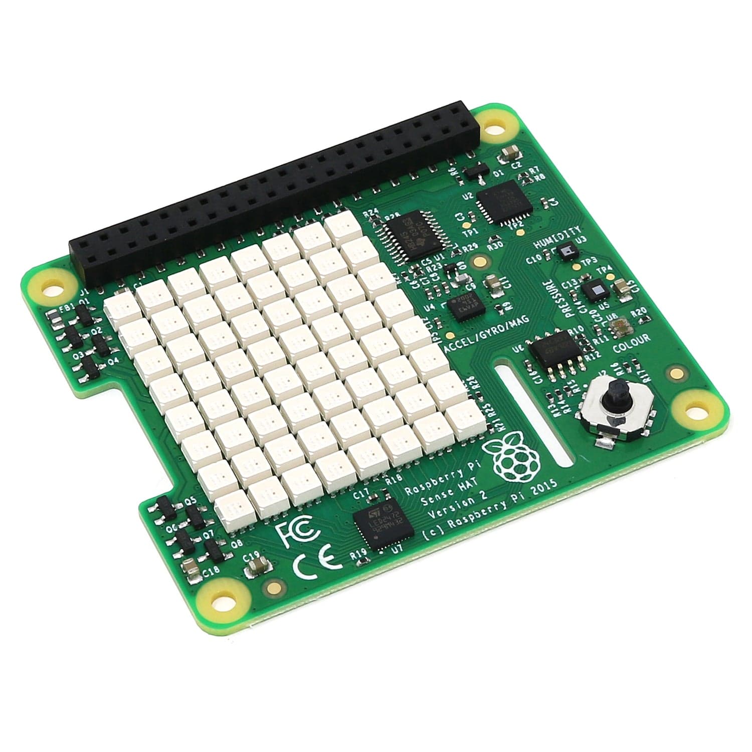
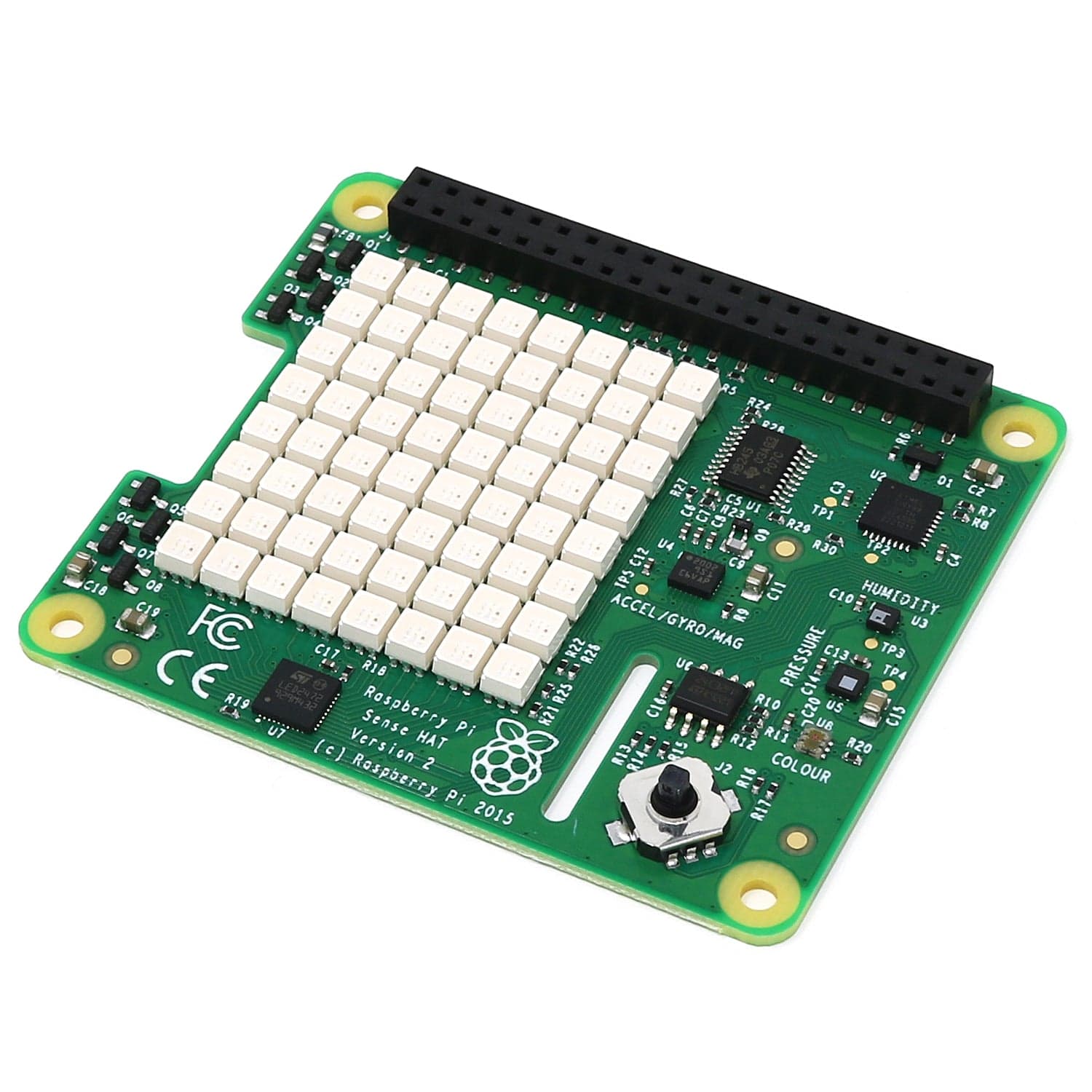
 HATs stands for Hardware Attached on Top and were first introduced in 2014. There are a series of rules that a board has to follow in order to be officially called a HAT (otherwise it’s just an add-on board). HATs can add support for any number of exciting features - from home automation to home arcades, even pianos, there are a number of exciting HATs currently on the market to add incredible features and none more so than official Raspberry Pi product, the Sense Hat.
The Sense Hat was created with young people in mind. There are currently two Sense Hats in the International Space Station, running code written by children as part of the Astro Pi competition. If you’re involved with schools or youth clubs in any way, it’s well worth getting involved with the Astro Pi competition which is run annually by the European Space Agency and Raspberry Pi Foundation in the Autumn.
What makes the Sense Hat special is that it has several built in sensors including a gyroscope, accelerometer and compass as well as temperature, pressure and humidity which gives children considering entering the competition the opportunity to think about the scientific implications of their data readings taken from space! It also has an 8x8 neopixel array and a joystick, which could be used for any number of interesting projects, however, in my mind, it’s a great tool if you fancy programming a quick game of snake on your display.
What about the pin numbers?
You may have noticed that the pin numbers don’t really seem to be in a logical order. Occasionally they are in numerical order, but more often than not, the pin numbers can be quite confusing!
It’s worth noting here that sometimes the pins are labelled differently to in the diagram above, but the most common numbering system is the one we’ve looked at which is known as BCM pin numbering (Broadcom pin numbering). You may occasionally find someone referring to ‘board’ or ‘physical’ numbering which involves just counting the pins and assigning a number to them, but BCM is much more common and is the number you will need to use if you want to use either Scratch or the GPIO Zero or RPi.GPIO libraries in Python. I tend to carry printouts of the pin numbers for workshops, but if you don’t have the patience, check out the PortsPlus board which just sits over the GPIO pins and clearly labels them (also available in a ruler form complete with handy Python hints). The idea behind PortsPlus is that it can sit underneath your projects and simply remain on the pins for quick reference.
So how does this work in practice?
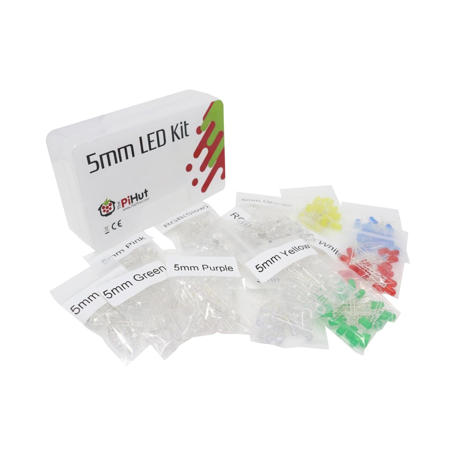
Let’s take a look at a simple LED circuit on a breadboard. Notice the blue cable is plugged into what would be the bottom right pin of the GPIO pin diagram? This means that I’ve connected the entire breadboard column into a ground pin so that anything I plug in below the blue cable will be ground.
The red cable runs from the row connected to the positive leg of the LED into the top right pin, labelled as pin 21.
Now we can write a program which will make our LED flash.. Let’s take a look at the program for both Scratch and Python:

In this script, we have used purple ‘set GPIO’ blocks which can be found in the ‘more blocks’ menu on Scratch 2.0 on the Raspberry Pi. You will see the number 21 in the GPIO label and then set it to either ‘output high’ or ‘output low’ to turn the LED on and off. We know from building the circuit that 21 is the number of the pin that we’ve connected the positive side of the LED to!

In order to flash an LED in Python, there needs to be a variable assigned to the appropriate pin number. In this case, on line 4, a variable called light has been declared as an LED on pin 21 so that when we called light.on() on line 7, the program knows that it needs to turn on the LED on pin 21. If you’d plugged your LED into a different numbered GPIO pin or added more LEDs onto different pins, you would need change the number in brackets to whatever the correct BCM pin number is.
Hopefully this has helped you to understand a little more about the GPIO pins on a Raspberry Pi. If you want to know where to go next, why not get yourself a CamJam Edukit, which provides all of the hardware you need to get started along with eight worksheets so that you can complete some simple physical computing projects with your Raspberry Pi.
For more information about the pins, check out Pinout.xyz which is a comprehensive quick reference guide.


