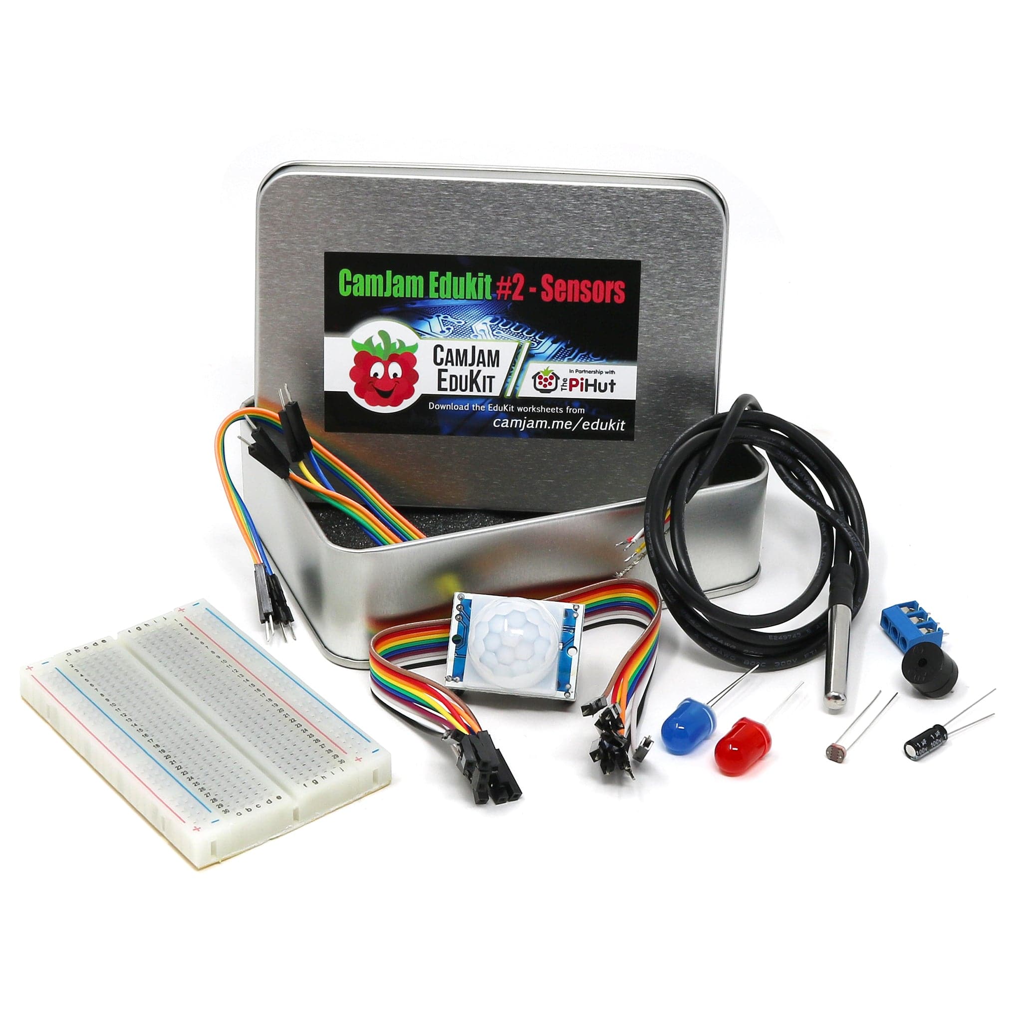
Sensors - Temperature with the 1-Wire interface and the DS18B20
Following on from last weeks' tutorial about using an i2c sensor, this week we are going to look at another standard protocol called '1-wire'. As the name suggests, this uses just one wire to communicate detailed information about the state of the sensor. The sensor actually needs three wires as power must be supplied, but the 1-wire refers to the data communication.
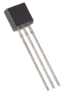
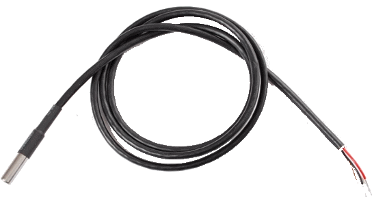
One of the common 1-wire sensors is the Dallas DS18B20 temperature sensor. This comes in different forms, with the main one looking like a transistor with three legs. The other form factor, and the one I prefer, is the waterproof version where the sensor is embedded in a metal tube on the end of a long wire.
Building the Circuit
You will need:
- A Dallas DS18B20 (either version)
- 4.7k ohm Resistor
- If there are four bands, the colours will be Yellow, Purple, Red, and then Gold
- If there are five bands, the colours will be Yellow, Purple, Black, Brown, Brown
- 4 female to male jumper wires
- 2 male to male jumper wires
Before building this circuit, you must turn the Raspberry Pi off.
The circuit will be using a ‘ground’ (GND) pin to act like the ‘negative’ or 0 volt ends of a battery. One of the pins marked 3v3 will provide the power for the sensor. 3v3 means that it is a 3.3 volt power supply.
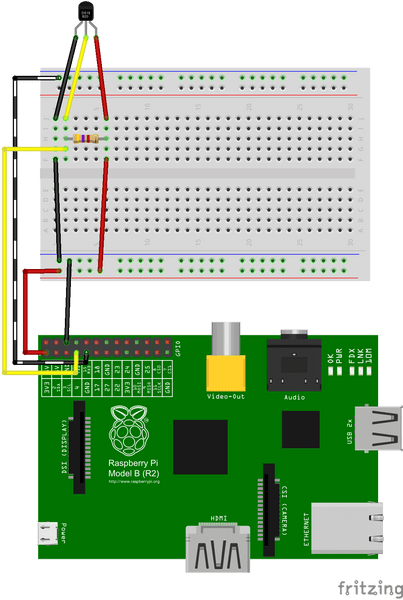
Use two female to male jumper wires to connect the GND and 3v3 GPIO pins to the bottom two rows of holes on the breadboard. Match up the colours marked on the breadboard - red and blue - with the jumper wires from the Raspberry Pi – connect 3v3 to the red row, and GND to the blue row. These two ‘rails’ (as they are known) will provide the ground and power supply for the whole of the breadboard.
Connect the temperature sensor as shown, with a male/male jumper wire going to the bottom ‘rail’ attached to the Raspberry Pi’s ground (GND). Connect the red wire using a jumper to the 3v3 ‘rail’ at the bottom. This supplies the temperature sensor with its power.
 If you are using the waterproof sensor, you may have problems pressing the wire strands into the breadboard holes. I use a terminal block and screw the wires into that.
The other end of the resistor should be inserted into another column of the breadboard, between the red lead of the temperature sensor and the jumper wire connected to the 3v3 ‘rail’. The yellow lead goes into a column with one end of the 4.7k ohm resistor and another jumper wire (shown in yellow) that goes to GPIO pin 4. The program will read the temperature from this pin.
Configuring your Raspberry Pi
Before you can use any 1-wire devices you must first tell the Raspberry Pi how to read them. Open a Terminal Window and type the following to edit the Raspberry Pi’s configuration file:
sudo nano /boot/config.txtLook to see whether there is a line that has dtoverlay=w1-gpio in it. If not, add the following to the end of the file:
dtoverlay=w1-gpioNow reboot the Raspberry Pi:
sudo rebootTo test the configuration, set-up the circuit above to connect the DS18B20 and type the following into a terminal window:
sudo modprobe w1-gpio
sudo modprobe w1-therm
cd /sys/bus/w1/devices
ls
This will list all the devices that are connected to the 1-wire interface. The Dallas DS18B20 sensor starts with ‘28-’ followed by a long number. Type in the following, replacing the ‘xxxx’ with the text following the ‘28-’:
cd 28-xxxx
cat w1_slave
In response, you should get the following showing that the DS18B20 is working:
a3 01 4b 46 7f ff 0e 10 d8 : crc=d8 YES
a3 01 4b 46 7f ff 0e 10 d8 t=32768
Reading from the Sensor
Create a new python script either from a terminal window (with nano 3-temperature.py) or from IDLE, the 'Interactive Development Environment'. Enter the following example code:
# Import Libraries
import os
import glob
import time

# Initialize the GPIO Pins
os.system('modprobe w1-gpio')  # Turns on the GPIO module
os.system('modprobe w1-therm') # Turns on the Temperature module

# Finds the correct device file that holds the temperature data
base_dir = '/sys/bus/w1/devices/'
device_folder = glob.glob(base_dir + '28*')[0]
device_file = device_folder + '/w1_slave'

# A function that reads the sensors data
def read_temp_raw():
  f = open(device_file, 'r') # Opens the temperature device file
  lines = f.readlines() # Returns the text
  f.close()
  return lines

# Convert the value of the sensor into a temperature
def read_temp():
  lines = read_temp_raw() # Read the temperature 'device file'

  # While the first line does not contain 'YES', wait for 0.2s
  # and then read the device file again.
  while lines[0].strip()[-3:] != 'YES':
    time.sleep(0.2)
    lines = read_temp_raw()

  # Look for the position of the '=' in the second line of the
  # device file.
  equals_pos = lines[1].find('t=')

  # If the '=' is found, convert the rest of the line after the
  # '=' into degrees Celsius, then degrees Fahrenheit
  if equals_pos != -1:
    temp_string = lines[1][equals_pos+2:]
    temp_c = float(temp_string) / 1000.0
    temp_f = temp_c * 9.0 / 5.0 + 32.0
    return temp_c, temp_f

# Print out the temperature until the program is stopped.
while True:
  print(read_temp())
  time.sleep(1)
To run the code, you need to be the Super User, so run the code with:
sudo python temperature.pyNow watch the temperature of the sensor as you hold it or put it in a glass of water (if you've got the waterproof one!).