Login / Signup
Cart
Your cart is empty


The Pololu 4-Channel RC Servo Multiplexer can be used with standard hobby radio control systems and servo controllers to allow easy switching of servo control between two independent sources using a separate auxiliary channel as the input selector. This makes it ideal for applications in which you have two possible control sources and want to be able to switch between them on the fly.
For example, you could connect two RC receivers to the same set of servos or electronic speed controls (ESCs) and allow the master transmitter to decide whether the master or slave transmitter is in control, thereby setting up your own buddy-system training setup. Another possible application would involve multiplexing between an RC receiver and a servo controller, which would allow you to switch between autonomous and manual control of a set of servos.
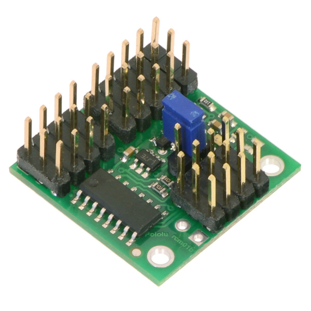
This assembled version ships with 0.1″-pitch male headers pins soldered in, so it can be integrated into hobby RC systems without the need for additional soldering.
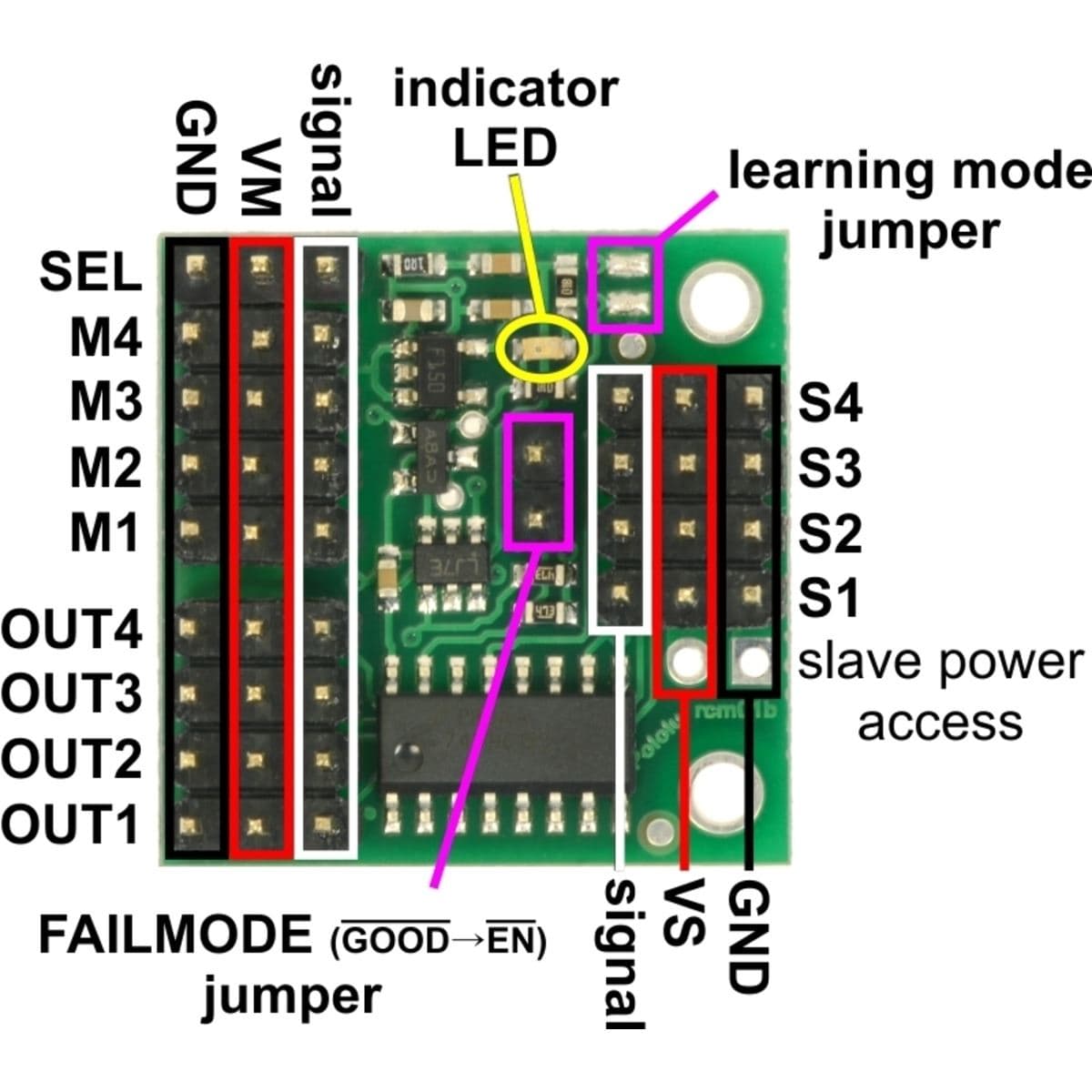
The RC multiplexer measures the width of incoming RC pulses on the channel labelled SEL and compares it to a user-configurable threshold (with ±64 μs of hysteresis) to decide whether the master (M1–M4) or slave (S1–S4) inputs to the mux should show up on the output channels (OUT1–OUT4). By default, the threshold is approximately 1700 μs and the slave inputs are only selected when the pulses on SEL are above this threshold. The multiplexer has a learning mode that allows you to change the threshold and activation direction. A yellow indicator LED provides feedback about the state of the RC mux.
When the RC signal on the SEL channel is lost or invalid, the optional FAILMODE jumper determines the output behaviour. If the jumper is left off, the master inputs will be in control. If the jumper is connected, the output channels go low and stay low for as long as the signal on the SEL channel remains invalid. For many servos and ESCs, a constant low on the signal line will turn them off, which might be desirable if the control signals are known to be bad.
The multiplexer considers the RC signal on the SEL channel to be valid if it has a 10–330 Hz pulse rate and 0.5–2.5 ms pulse width. The other inputs (S1–S4 and M1–M4) are unrestricted.
The power supplied by the master RC device should be between 2.5 and 16 V, and it must be capable of supplying the current that the servos connected to the outputs draw. The power pins of the SEL, M1–M4, and OUT1–OUT4 channels are all connected to the same VM rail, and the mux draws its power from those pins. The power pins of the S1–S4 inputs are connected to each other on the VS rail but are not used by the board.
More information about using this product can be found in the user’s guide.
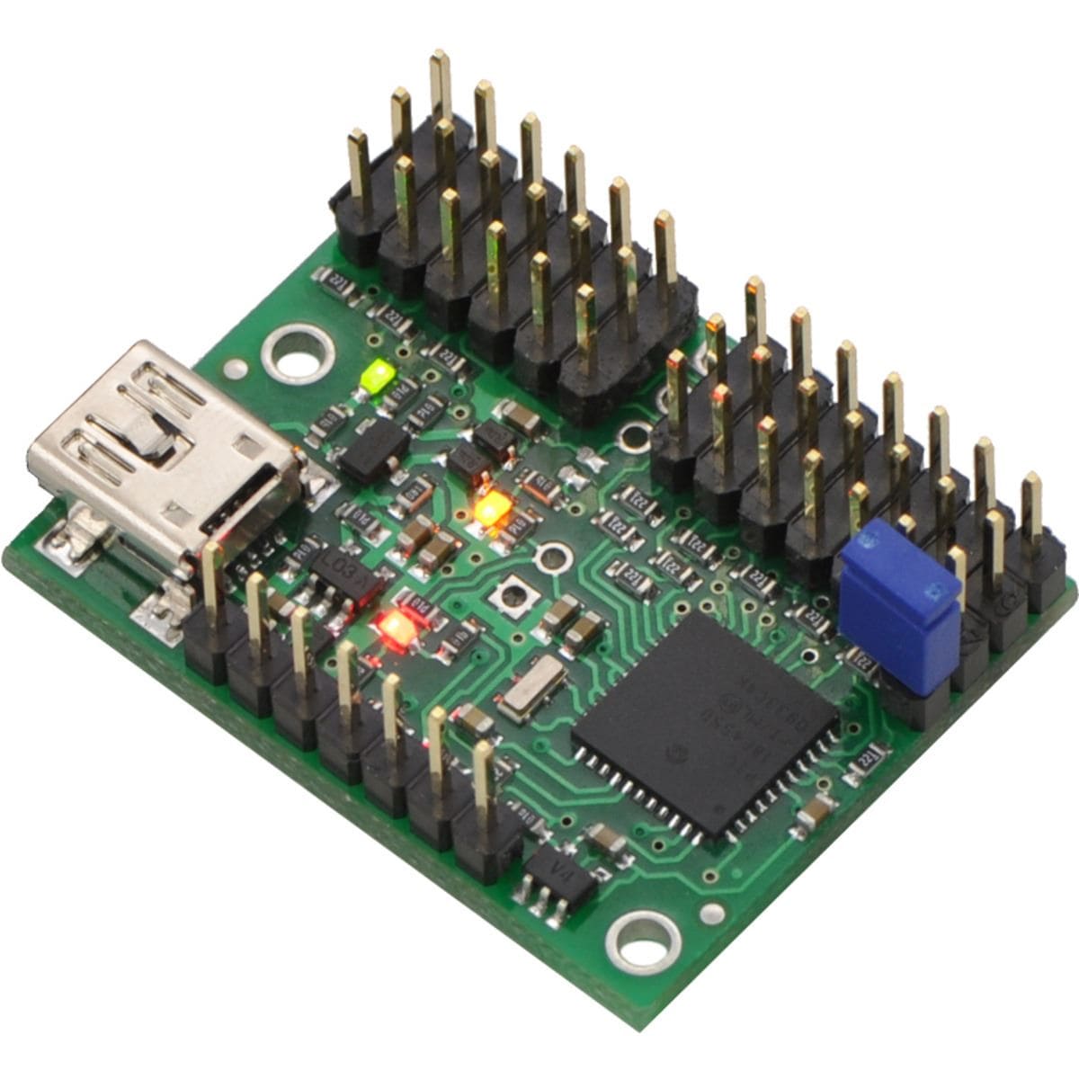
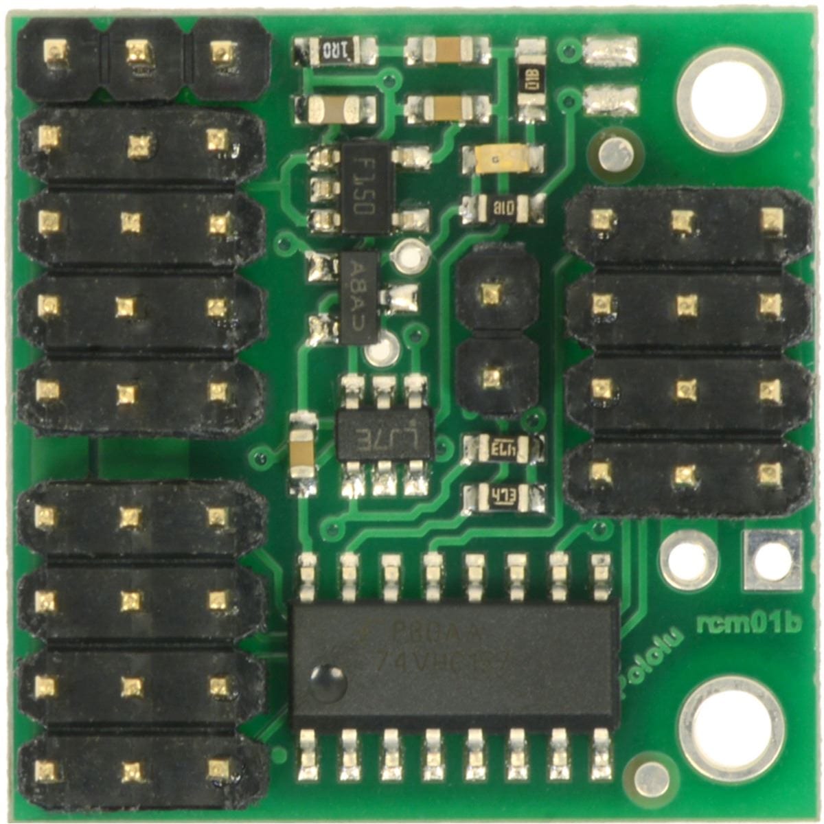
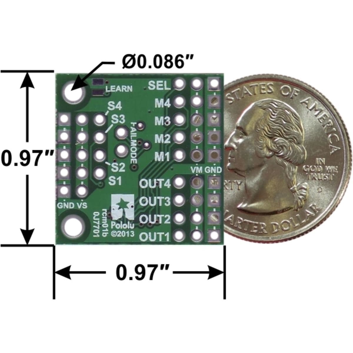
This assembled version ships with the headers pins soldered into every through-hole except the extra slave power connection pins, as shown in the images. A shorting block is included for optional use with the FAILMODE jumper pins.
The assembled version can be incorporated into an existing RC system without the need for any additional soldering. The header pin spacing is the same as on standard RC receivers, so the board works directly with standard hobby RC servos and servo cables.
The RC multiplexer is essentially the Pololu RC Switch with digital output combined with a quad 2-input multiplexer. The LED behaviour and configuration procedures are the same.
However, the RC switches have a safe-start feature that is not enabled on the RC multiplexer. The RC switches have a GOOD output that is high when the signal is good, while the RC multiplexer has a GOOD output that is low when the signal is good (this signal can be accessed via the upper/octagonal pad of the FAILMODE jumper). The RC switches have an OUT output that indicates whether the switch is active; the RC multiplexer has the same signal, but it is not easily accessible.


