Login / Signup
Cart
Your cart is empty


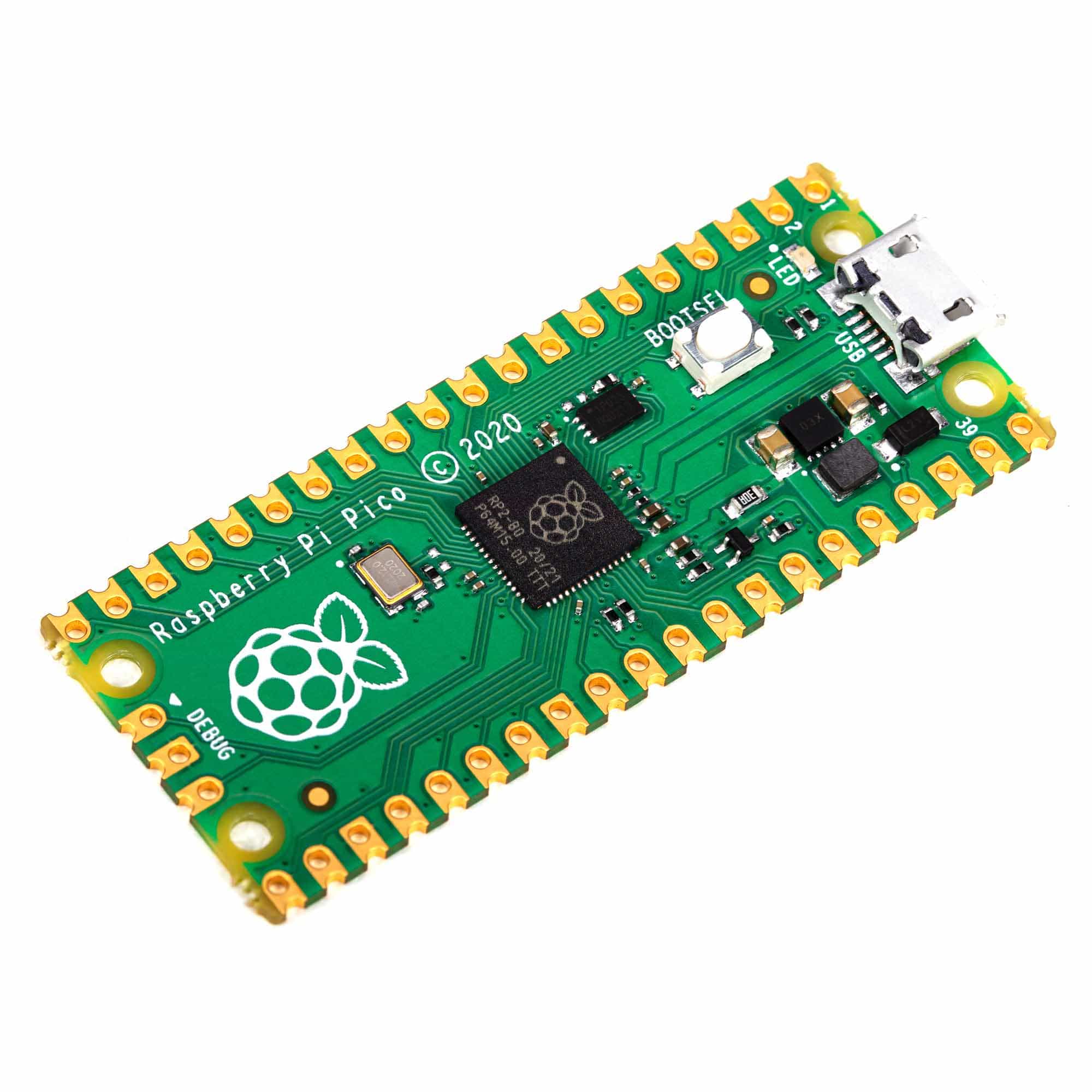
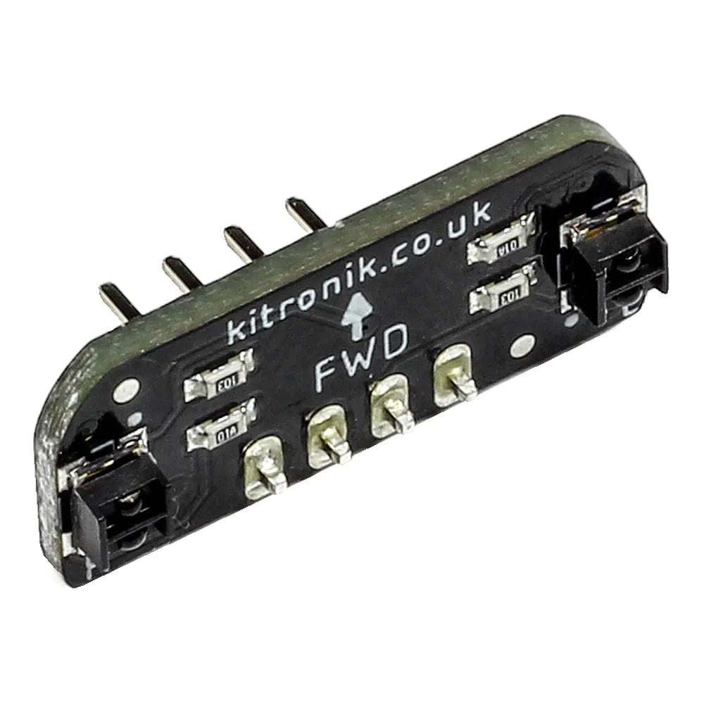
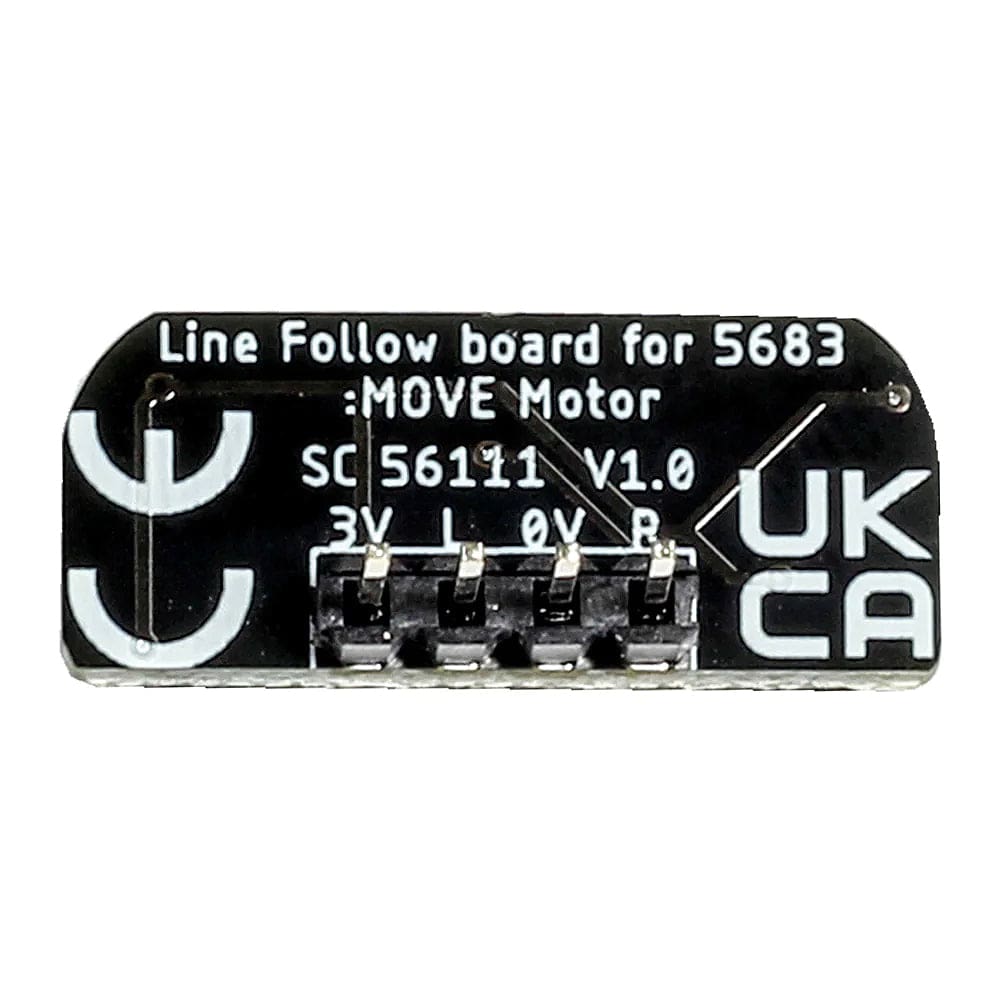
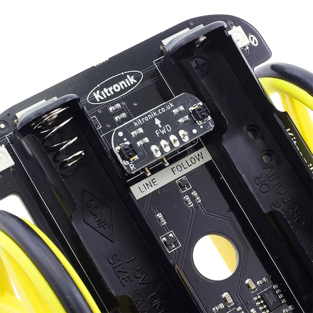
The :MOVE Line Following sensor board adds line following sensors to a project. The 2 LED/phototransistor sensors output an analogue voltage that can be read into a microprocessor’s ADC channel. Although designed for use with the MOVE Motor for BBC micro:bit, this board can be used with other boards, such as; Arduino and Raspberry Pi Pico, as well as other micro:bit buggy/robot projects.
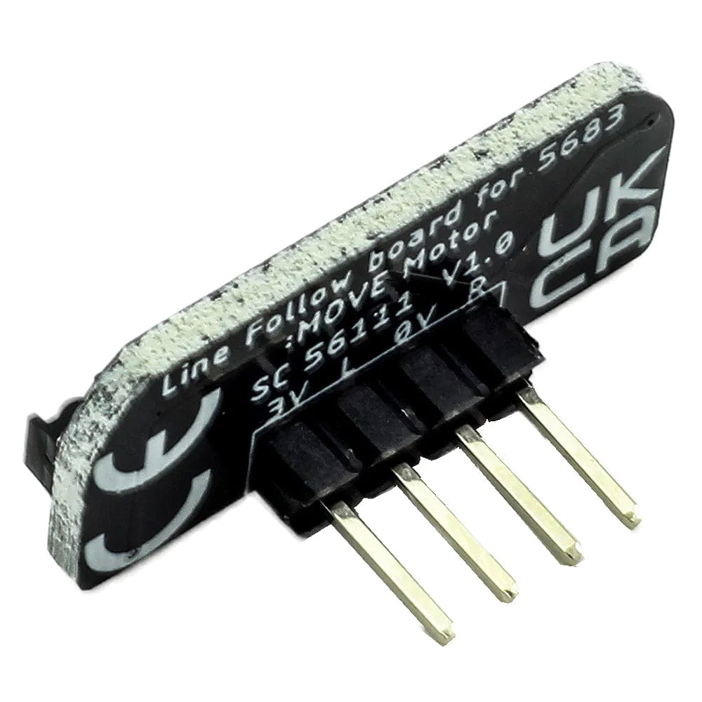
The board features the following connections; The 4-pin connections are on a standard 0.1” (2.54mm) pitch. The pins provide connections for power (3V and 0V) and 2 sensor outputs, marked L and R for the left and right sensors respectively.
The board requires a 3V - 5V (typically 3.3V) and a ground connection onto the pin header. These pins are marked on the board as 3V and 0V.
The sensor output voltage changes from the supply voltage to 0V as the sensors pass over light and dark surfaces. Different surfaces will reflect different amounts. A typical light surface will give a value of 0.5V for example. A typical dark surface will give a value of 2.5V (assuming a 3V VCC). The value in a program will depend on the processor's ADC range and width.
| Surface | Response |
| Light. | Low Voltage ˜ 0V |
| Dark. | High Voltage ˜ 3V |
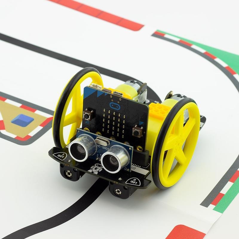
The MakeCode online tutorial is available to show how the sensors can be used for line following. Although this tutorial is for :MOVE Motor, the same principles can be applied to other buggies/microcontrollers.


