Pololu Basic SPDT Relay Carrier with 5VDC Relay (Assembled)
Price:
Sale price
£7.30
Stock:
Quantity:
 Skip to content
Login / Signup
Cart
Your cart is empty


The Pololu basic relay carrier modules allow simple control of a single-pole, double-throw (SPDT) switch from low-voltage, low-current control signals.
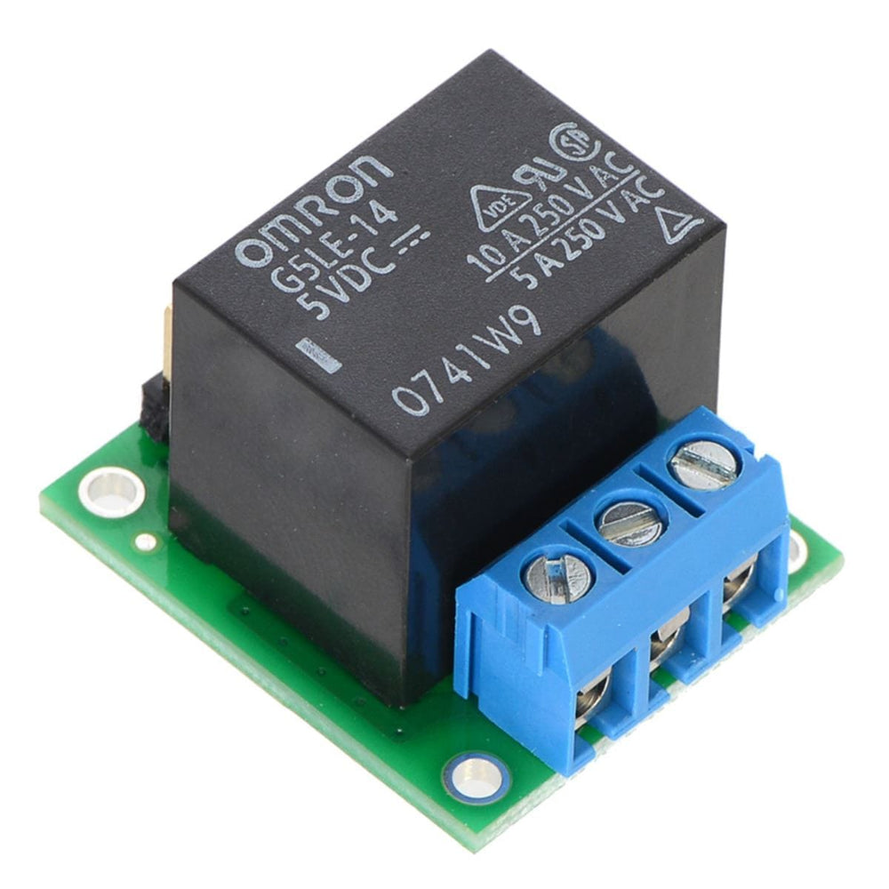
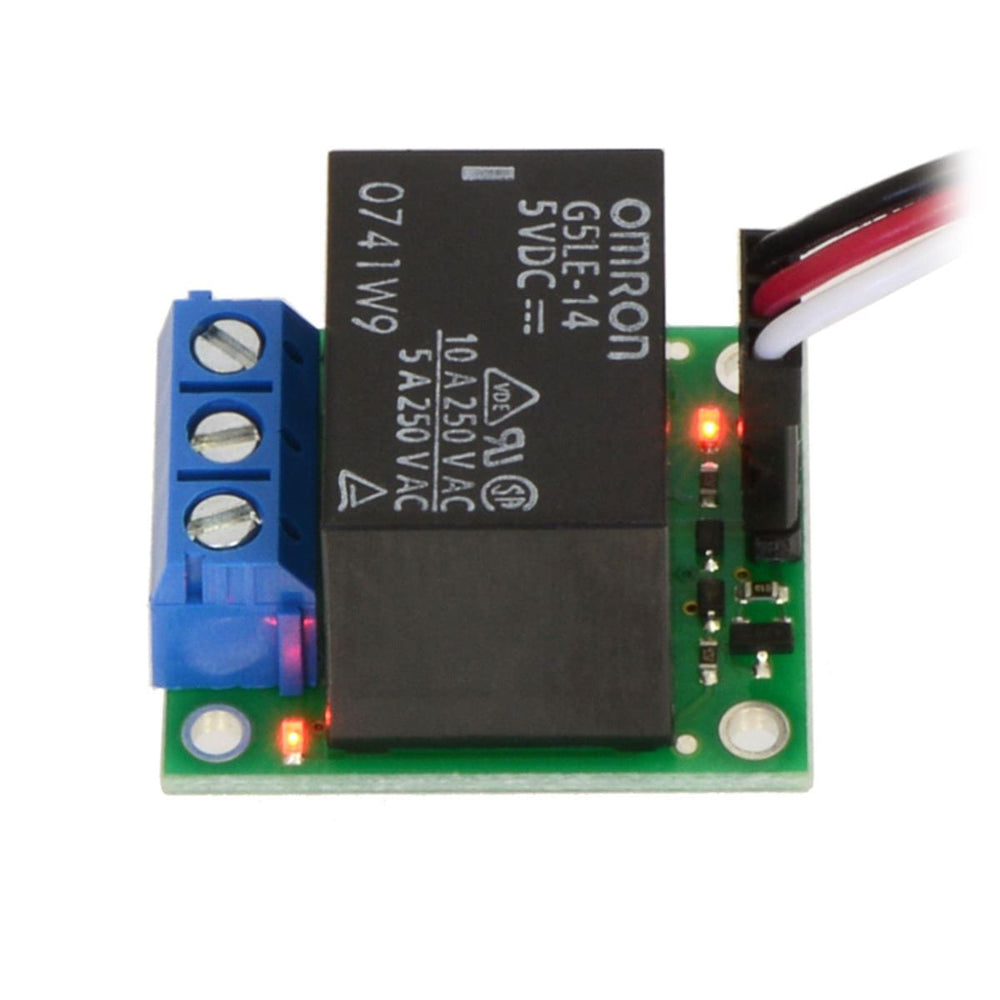
This item includes the basic carrier PCB with a soldered-in 5V relay, 5.0 mm terminal blocks for the switch connections, and straight 0.1" male header for the control connections. The included power relay is an Omron G5LE-14-DC12 and is rated for up to 10A under most conditions.
We also offer a dual-channel version and a partially-assembled kit.
Warning: This product is not designed to or certified for any particular high-voltage safety standard. Working with voltages above 30V can be extremely dangerous and should only be attempted by qualified individuals with appropriate equipment and protective gear.
The Pololu basic relay carrier modules make it easy to control a single-pole, double-throw (SPDT) switch from low-voltage, low-current control signals.
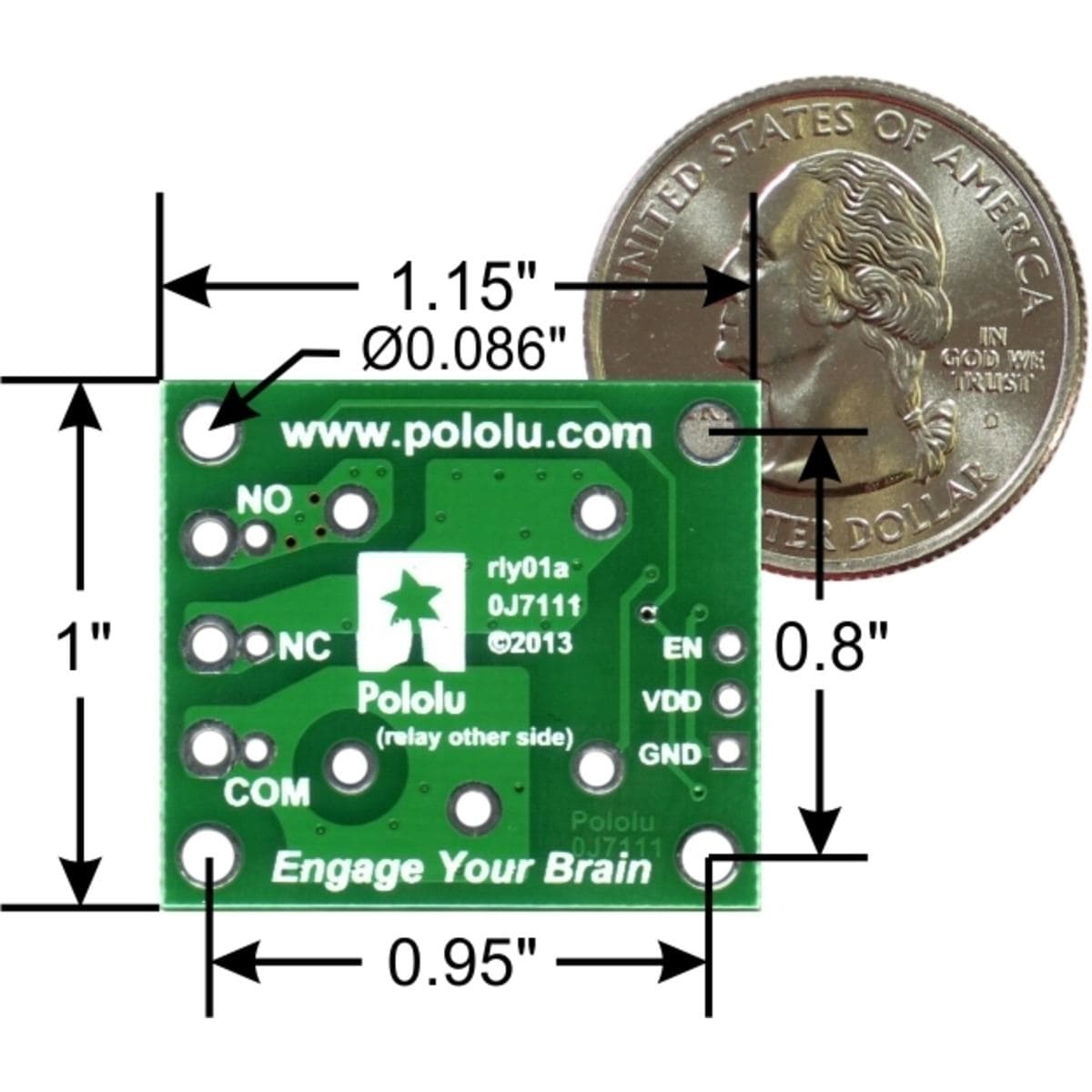
The carrier board routes the three relay control pins to 0.1″-spaced pins compatible with standard solderless breadboads and female servo cable connectors. This assembled version of this board has a 0.1″ straight male header soldered to these pins.
The relay switch pins are routed to a set of large pads intended for use with a 3-pin 5mm-pitch terminal block and a set of smaller pads with a 0.2″ pitch, making them compatible with 0.1″ perfboards. This assembled version of this board has a terminal block pre-soldered to these pins. The carrier board has four mounting holes that work with #2 or M2 screws.
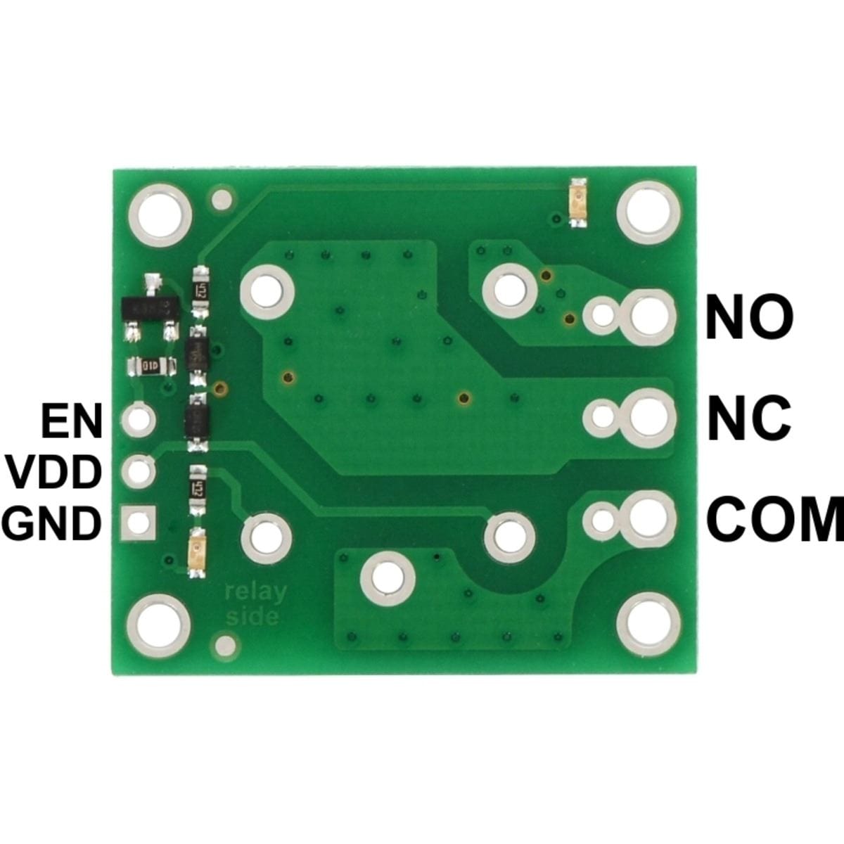
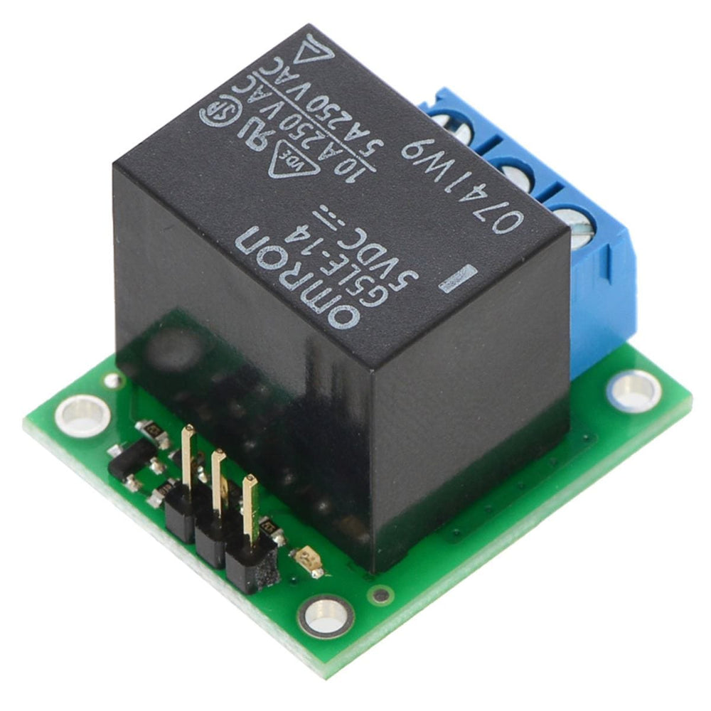
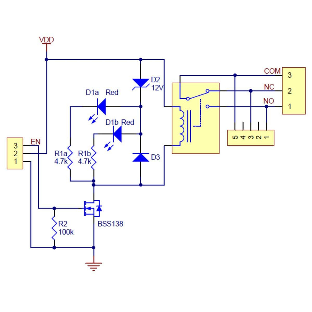
The switch portion of the relay is accessible on one side of the board while the control pins are routed to the other. The relay coil is powered by supplying the appropriate coil voltage for your specific relay across the VDD and GND pins, and it is activated by a digital high control signal on the EN pin.
The control signal is fed directly to a BSS138 N-channel MOSFET, which in turn actuates the relay coil when the control voltage exceeds approximately 2.5 V, up to a maximum of 20 V (see BSS138 datasheet for details).
The relay switch terminals COM (common), NO (normally open), and NC (normally closed) are routed on the PCB with a minimum clearance of 60 mils (1.5 mm) from other copper. The copper traces are designed to be at least 45 mil (1.1 mm) from the board edges, though manufacturing variations in the board edges can make those distances slightly lower.
In most applications, the current and voltage ratings for the module will match the ratings of the relay used. Maximum current, maximum voltage, and life expectancy are interdependent; we, therefore, recommend careful examination of your relay’s datasheet.

Your payment information is processed securely. We do not store credit card details nor have access to your credit card information.