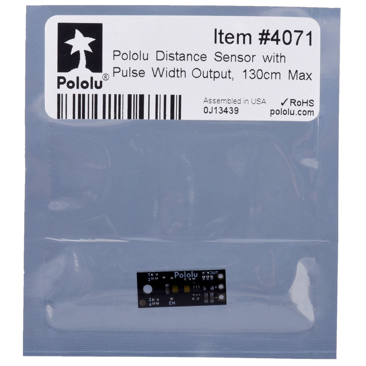
Pololu Distance Sensor with Pulse Width Output - 130cm
Price:
Sale price
£22.10
Stock:
Quantity:
Login / Signup
Cart
Your cart is empty


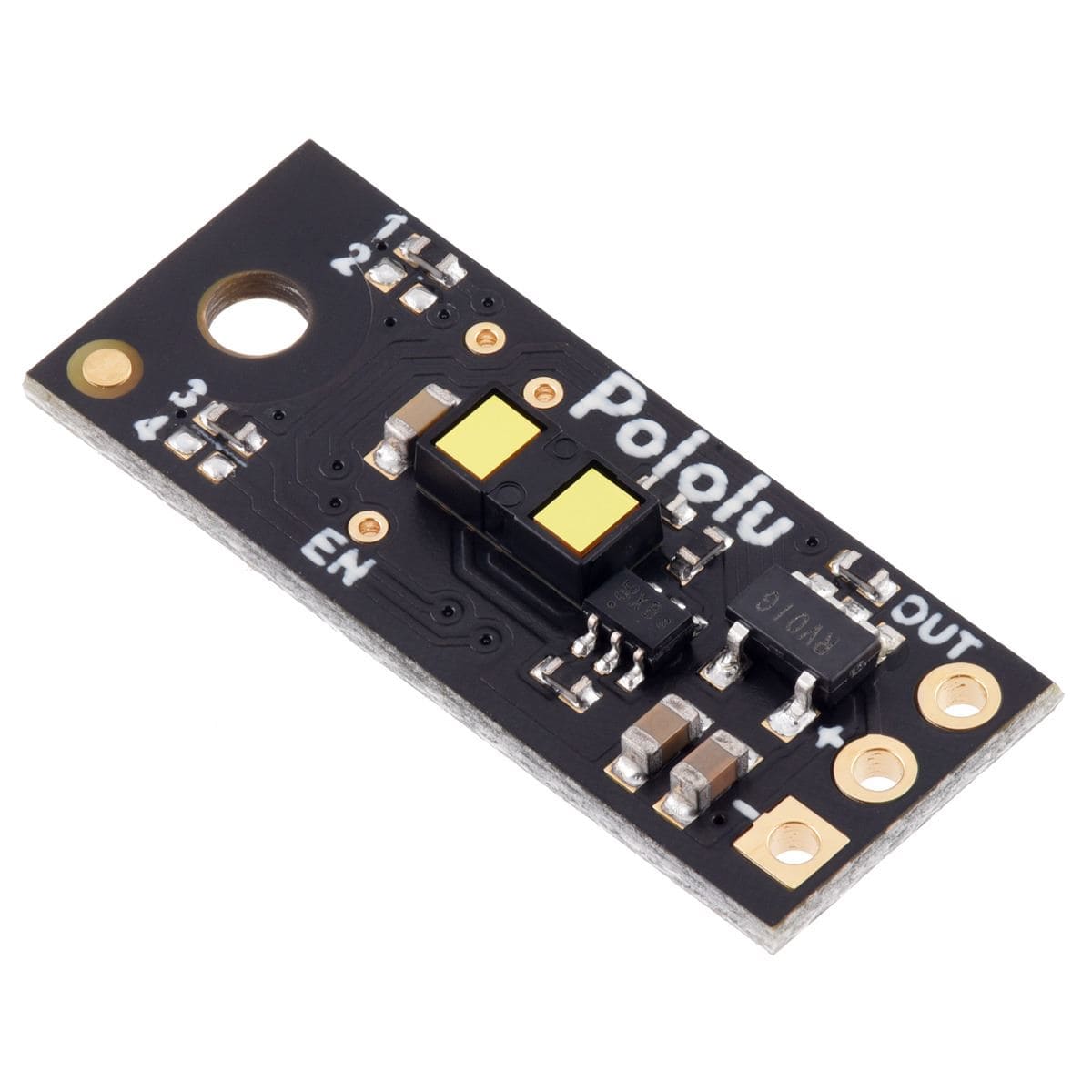
This small Pololu lidar-based distance sensor reports the distance of objects up to about 130cm away with a pulsed signal similar to a hobby servo control signal.
It uses a short-range lidar module to precisely measure how long it takes for emitted pulses of infrared, eye-safe laser light to reach the nearest object and be reflected back, allowing for 1 mm resolution. As long as the sensor is enabled, it takes continuous distance measurements and encodes the ranges as the widths of high pulses, which can then be timed by a microcontroller using a single digital input.
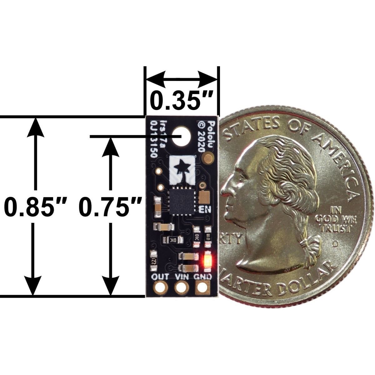
The sensor works over an input voltage range of 3.0V to 5.5V, and the 0.1″ pin spacing makes it easy to use with standard solderless breadboards and 0.1″ perfboards.

Note: The maximum range of 130cm is only achievable for high-reflectance objects in good ambient conditions. Lower-reflectivity targets or poor ambient conditions will reduce the maximum range. Also available in 50cm and 300cm versions.
The relationship between measured distance d (in mm) and pulse width t (in µs) is as follows:

The timing uncertainty is approximately ±5%. As objects approach the sensor, the output pulse width will approach 1.0 ms, while an object detected at 130 cm will produce a 1.65 ms pulse width. The sensor uses a pulse width of 2.0 ms to indicate no detection. The pulse period T ranges from around 9 ms to 10 ms, depending on the proximity of the detected object.
The maximum detection range depends on object reflectivity and ambient lighting conditions. In our tests, the sensor was able to reliably detect a white sheet of paper out to around 130 cm away, and it could reliably detect a hand out to around 80 cm away. The following graph shows the measured distances of five units versus their actual distances from a white paper target at several different ranges:

Please note that while this sensor can detect objects to within about 1 mm of the sensor face, the effective minimum distance it can measure is around 4 cm, so objects closer than 4 cm might result in an inaccurate measurement.
Important note: This product might ship with a protective liner covering the sensor IC. The liner must be removed for proper sensing performance.


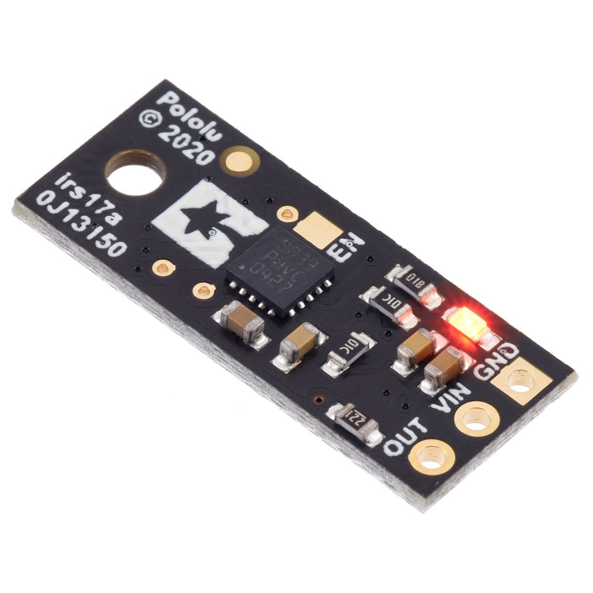
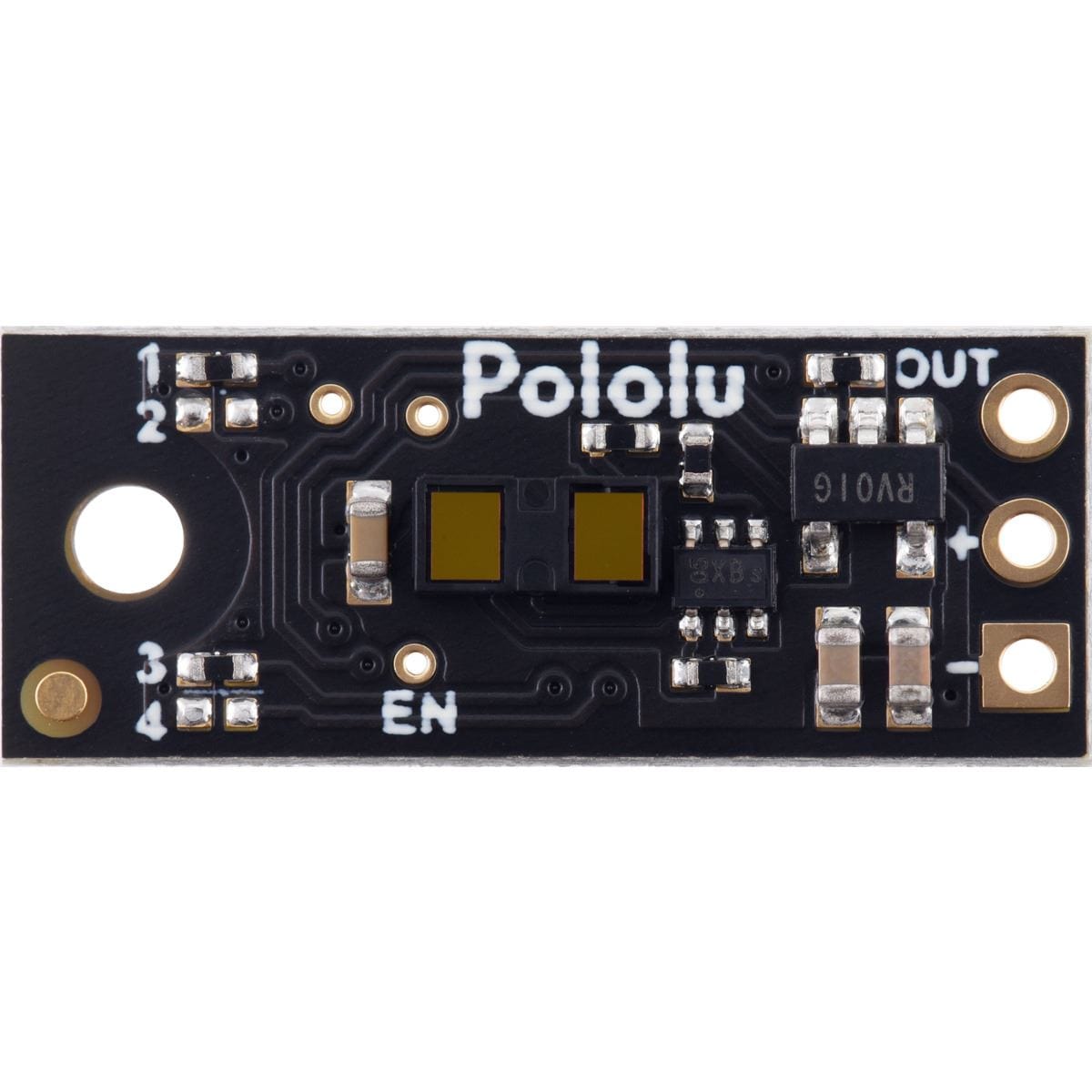
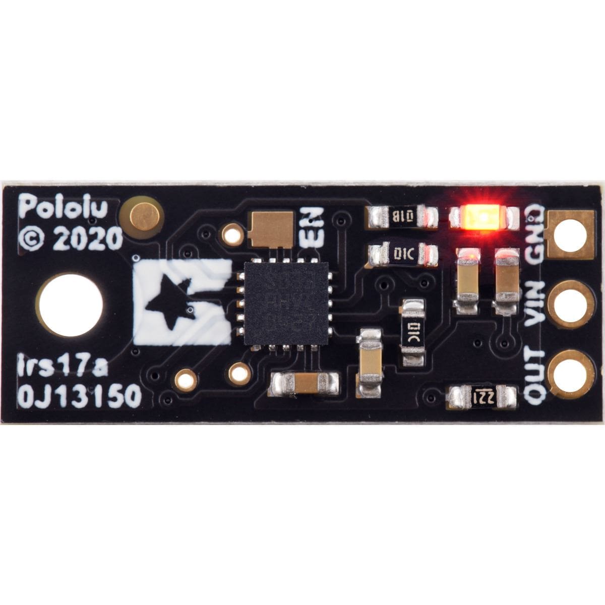
Three connections are necessary to use this module: VIN, GND, and OUT. These pins are accessible through a row of 0.1″-pitch through holes, which work with standard 0.1″ (2.54 mm) male headers and 0.1″ female headers (available separately). The VIN pin should be connected to a 3 V to 5.5 V source, and GND should be connected to 0 volts. The sensor outputs its digital pulses on the OUT pin. The low level of the pulses is 0 V, and the high level is VIN. A red LED on the back side of the board also lights whenever an object is detected (the closer the object, the brighter the LED).

The board has an optional ENABLE pin that can be driven low to put it into a low-power state that consumes approximately 0.4 mA. This pin can be accessed through a via or its neighboring surface-mount pad on the back side labelled “EN” on the silkscreen. The ENABLE pin is pulled up to VIN, enabling the sensor by default.
The board has one mounting hole intended for use with #2 or M2 screws.
This is a simple Arduino sketch that reads the output of the Pololu Distance Sensor with Pulse Width Output, 130cm Max and displays the measured distance in millimeters.
// Example Arduino program for reading the Pololu Distance Sensor with Pulse Width Output, 130cm Max

// Change this to match the Arduino pin connected to the sensor's OUT pin.
const uint8_t sensorPin = 2;

void setup()
{
  Serial.begin(115200);
}

void loop()
{
  int16_t t = pulseIn(sensorPin, HIGH);

  if (t == 0)
  {
    // pulseIn() did not detect the start of a pulse within 1 second.
    Serial.println("timeout");
  }
  else if (t > 1850)
  {
    // No detection.
    Serial.println(-1);
  }
  else
  {
    // Valid pulse width reading. Convert pulse width in microseconds to distance in millimeters.
    int16_t d = (t - 1000) * 2;

    // Limit minimum distance to 0.
    if (d < 0) { d = 0; }

    Serial.print(d);
    Serial.println(" mm");
  }
}
We have also created a MakeCode example program for the BBC micro:bit single-board computer that demonstrates how to read and convert the output of the Pololu Distance Sensor with Pulse Width Output, 130cm Max. The program’s output can be viewed in the MakeCode device console, which also plots the readings on a graph.
These Pololu Digital Distance Sensors have the same form factor and pinout as our carrier boards for the Sharp/Socle GP2Y0D8x digital distance sensors. They are available in the same 5 cm, 10 cm, and 15 cm ranges, in addition to longer ranges of up to several meters.
This means they can be used as replacements for these older modules, which are based on sensors from Sharp/Socle that are no longer in production, and the longer-range versions can serve as upgrades that provide enhanced detection and measurement capabilities. The sensors on these newer units are much thinner than the Sharp modules, so the zero-range point is approximately 7 mm closer to the PCB, and the beam angle of the newer units is wider.
Your payment information is processed securely. We do not store credit card details nor have access to your credit card information.