Adafruit Metro RP2040
Price:
Sale price
£14.40
Stock:
Quantity:
 Skip to content
Login / Signup
Cart
Your cart is empty
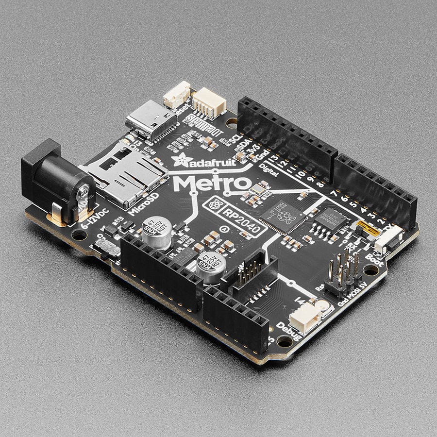
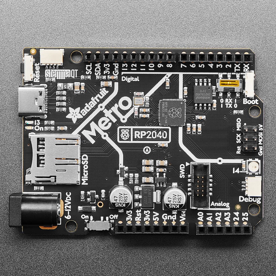
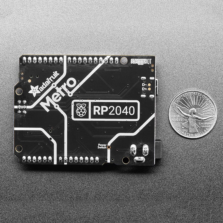
Choo! Choo! This is the RP2040 Metro Line, making all station stops at "Dual Cortex M0+ mountain", "264K RAM round-about" and "16 Megabytes of Flash town". This train is piled high with hardware that complements the Raspberry Pi RP2040 chip to make it an excellent development board for projects that want Arduino-shape compatibility or need extra space and debugging ports.
You may be wondering about the RX-TX switch: we added this because traditional Arduino boards start counting the GPIO for the digital pins with 0-7 and then 8-13. However, the D0/D1 pins are also traditionally the hardware UART Serial1, where D0 is Rx and D1 is Tx. On the RP2040, however, the UART pins are the other around: D0 is Tx and D1 is Rx. Thus a DPDT switch: flip one way to have the GPIO go in order of 0-7, flip the other way to have the logical locations of the hardware UART correct but now the pin order is 1, 0, 2, 3..7. Of course, it's also handy if, like us, you often swap the pins - now you don't need to require or cut/solder traces!
The RP2040 is a powerful chip with the clock speed of our M4 (SAMD51) and two cores that are equivalent to our M0 (SAMD21). Since it is an M0 chip, it does not have a floating point unit or DSP hardware support - so if you're doing something with heavy floating-point math, it will be done in software and thus not as fast as an M4. For many other computational tasks, you'll get close-to-M4 speeds!
For peripherals, there are two I2C controllers, two SPI controllers, and two UARTs that are multiplexed across the GPIO - check the pinout for what pins can be set to which. There are 16 PWM channels, each pin has a channel it can be set to (ditto on the pinout).
You'll note there's no I2S peripheral, or SDIO, or camera, what's up with that? Well, instead of having specific hardware support for serial-data-like peripherals like these, the RP2040 comes with the PIO state machine system, a unique and powerful way to create custom hardware logic and data processing blocks that run independently without taking up a CPU. For example, NeoPixels - often we bit-bang the timing-specific protocol for these LEDs. For the RP2040, we instead use a PIO object that reads in the data buffer and clocks out the right bitstream with perfect accuracy. Same with I2S audio in or out, LED matrix displays, 8-bit or SPI-based TFTs, and even VGA! In MicroPython and CircuitPython, you can create PIO control commands to script the peripheral and load it in at runtime. There are 2 PIO peripherals with 4 state machines each.
There is great C/C++ support, unofficial (but really good) Arduino support, an official MicroPython port, and a CircuitPython port! We, of course, recommend CircuitPython because we think it's the easiest way to get started, and it has support with most of our drivers, displays, sensors, and more, supported out of the box so you can follow along with our CircuitPython projects and tutorials.
While the RP2040 has lots of onboard RAM (264KB), it does not have built-in FLASH memory. Instead, that is provided by the external QSPI flash chip. On this board, there is 16 MB, which is shared between the program it's running and any file storage used by MicroPython or CircuitPython. When using C/C++, you get the whole flash memory, if using Python, you will have about 7 MB remaining for code, files, images, fonts, etc.
Your payment information is processed securely. We do not store credit card details nor have access to your credit card information.