Challenger RP2040 LTE MkII
Price:
Sale price
£57
Stock:
Quantity:
 Skip to content
Cart
Your cart is empty


The iLabs Challenger 2040 LTE Mk2 is an Arduino/Micropython compatible Adafruit Feather format microcontroller board with an LTE modem and battery charging circuit, based on the Raspberry Pi RP2040!
This board has been designed to allow you to create inexpensive IoT devices that can be deployed anywhere without having to depend on a WiFi connection or a tethered phone. This just works wherever you are (as long as you have LTE signal!). It connects seamlessly to the same network that your phone does and allows you to transfer your data quickly and with very short delays.
By using the powerful dual-core RP2040 combined with 8Mbyte of flash memory you get a device that can handle pretty much anything you can throw at it. For instance, if you let one core handle the LTE modem and the second core handle the UI you get an extremely responsive system. Not to mention that the 8MByte of FLASH memory will let you install any (or all) CircuitPython support libraries that you will ever need.
The flash memory can be used both to store instructions for the microcontroller as well as data in a file system and having a file system available makes it easy to store data in a structured and easy to program approach.
The device can be powered by a Lithium Polymer battery connected through a standard 2.0mm connector. An internal battery charging circuit allows you to charge your battery safely and quickly. The device is shipped with a programming resistor that sets the charging current to 250mA.
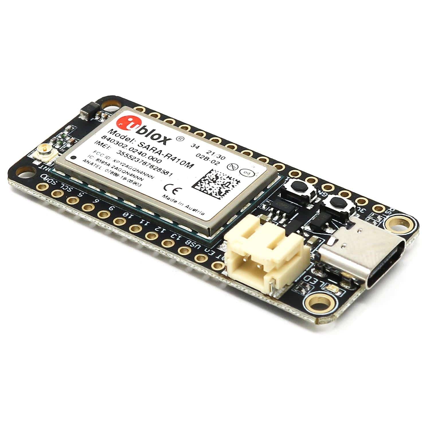
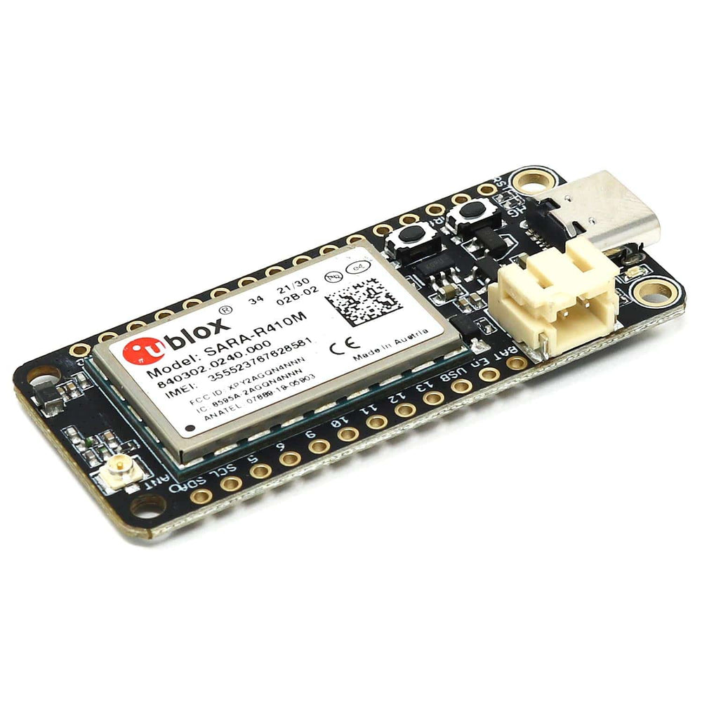
The LTE section of this board is based on UBlox LTE modem SARA R410M that is connected to the microcontroller through one of its internal UARTs.The modem is controlled using standard AT-commands that allow the user to connect the device to an LTE network to send and receive data.
MkII! The new MkII version has an improved power supply section that reduces power consumption and allows the board to run at a lower battery voltage than before. Which in the end leads to longer battery operating times.
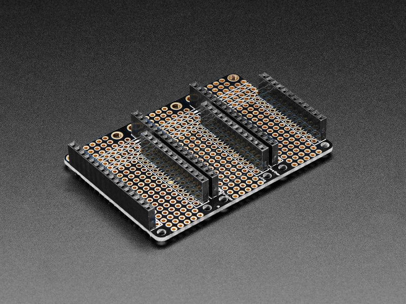
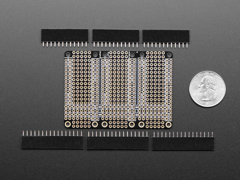
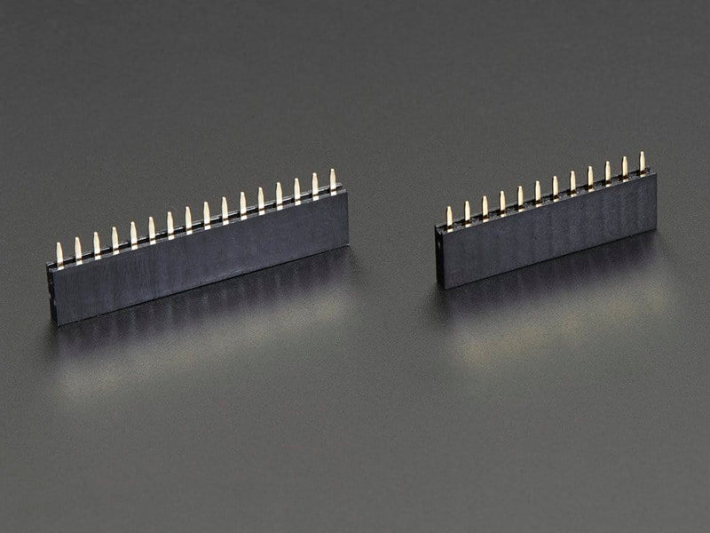
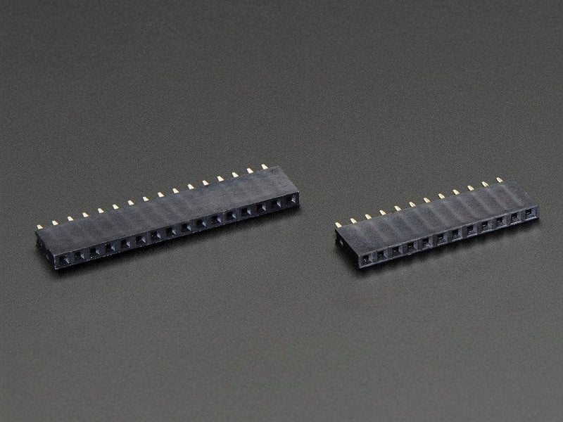
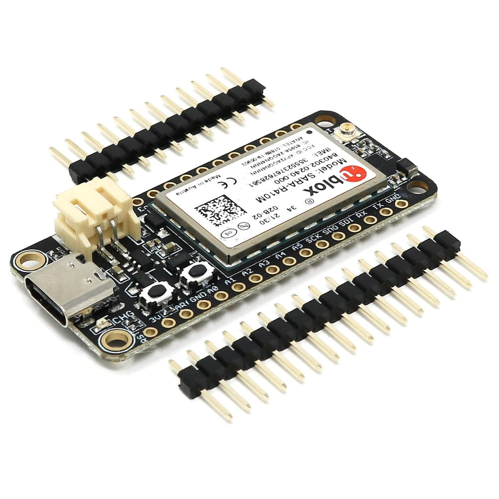
A set of headers are included with the board.
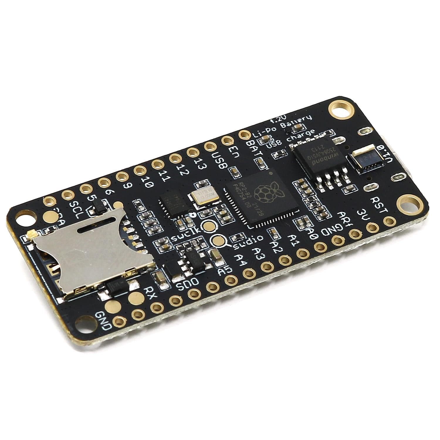
Again we have used the popular RP2040 from the Raspberry Pi Pico. An extremely well suited embedded processor for doing cool projects and managing high-end communication devices such as the embedded modem. With its dual-core Cortex M0 at 133MHz, 8 MByte of FLASH and 264 Kbyte of integrated RAM it will take a very long time before you run out of resources.
The module we selected to handle cellular communication is the SARA-R410M series module. This module can be software multi-band configured, enabling international multi-regional coverage in LTE-M/NB-IoT radio access technologies.
The SARA-R410M module is ideal for mission-critical IoT solutions, as it includes a unique and immutable root of trust. It supports IoT security as a service and provides the foundation for a trusted set of advanced security functionalities. The scalable, pre-shared key management system offers data encryption and decryption, both on-device as well as from device to cloud. Utilizing the latest (D)TLS stack and cipher suites with hardware-based crypto acceleration provides robust, efficient and protected communication.
Communication with the modem device is done over the second serial port of the RP2040 and the board is configured for hardware flow control which allows you to use high data transfer speeds to and from the modem.
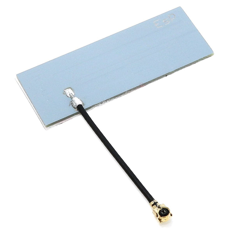
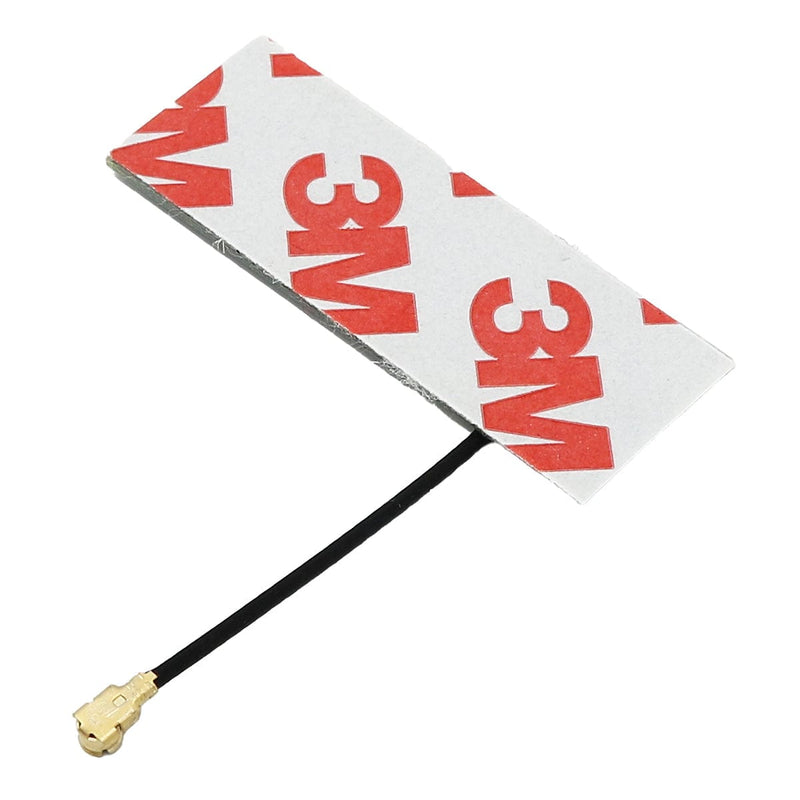
The supplied cellular antenna is connected to the board through a U.FL connector at the rear of the board. The antenna can then be attached to a plastic enclosure by peeling off the protective film and pressing it in place.
The board needs a nano-SIM card in order to be able to connect to an LTE network and transfer data.
On the opposite end from the USB connector, there is a small U.FL connector where an LTE antenna should be connected. The antenna must have a 50ohm impedance and should be mounted according to the manufacturer’s specifications.
The board can be powered from multiple sources. The most obvious way to run the board is by plugging it into a USB cable and attaching it to your computer. In this mode, you can write software and test the board with all its functionality.
There is also a third way to supply the board. This way is more invasive and will disable the onboard 3.3V power regulator.
You will have to pull the EN header pin low and then supply your own 3.3V voltage on the 3.3V header pin. Please note that when disabling the onboard power regulator you will have to supply the 3.3V also when running the system on battery power.
As described earlier the board can be powered from a LiPo battery. The battery can be connected using a standard 2.0mm JST connector through the battery connector on the right side of the board or ff the battery is an integral part of the system that you are designing it is possible to connect the battery through the BAT pin instead.
Switching between the battery voltage and the applied USB voltage or external 5V is done seamlessly by the onboard circuitry.
Charging of the battery is done by either connecting a USB cable or by connecting a 5V power source to the header pin marked USB on the board. If you do this make sure you connect your voltage through a 1A Schottky diode to avoid any excessive current draw in the system when the two levels are slightly different.
Please note that providing external charger circuitry could destroy the internal charger on the Challenger board.
There are two buttons on the board. The button closest to the USB connector is the reset button. Use it whenever you need to reset the unit. It has exactly the same functionality as the RESET pin.
Then there is the BOOT button just next to the reset button. This button must be used in conjunction with the reset button to reset the RP2040 into UF2 mode. Press the BOOT button, then the RESET button for a short moment. Then release the RESET button (while still pressing the BOOT button) and shortly after that release the BOOT button. This will place the board in UF2 mode and show up in the computer as a mass storage device.
On each side of the USB connector, there is a small indicator LED placed. The LED which is marked CHG is the charge control indicator. This red LED will shine whenever the connected battery is being charged, and when the battery is fully charged the LED will turn off again. If you haven’t connected a battery to the board this LED will not come on at all.
On the other side of the USB connector, there is a user-programmable green LED. This LED is connected to pin D15 and can easily be controlled by the user program.
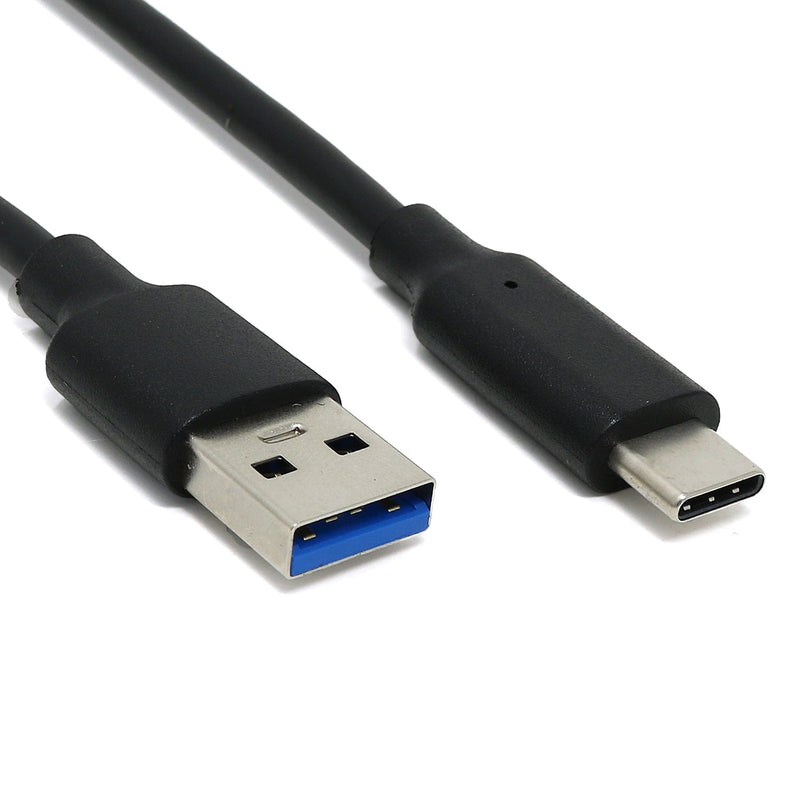
In recent years we have noticed that we are seeing more and more USB Type-C cables laying around the lab due to the fact that most new phones and accessories use them. So iLabs decided to go for a USB Type-C connector for this board. A bonus of this is that they are more durable and you don’t have to fiddle with the cable before plugging it in!
The board uses the second UART (UART 1) of the MCU to connect to the LTE modem. In addition to the RXD and TXD signals the RTS and CTS signals are also connected to support large data transfers. Three more GPIO pins are connected to the power on and reset pin of the device.
| Description | Value | Comment |
| Board Size | 50,80 mm x 22,86 mm x 3,20 mm | USB Connector protrudes ~1mm outside PCB |
| Main microcontroller | RP2040 from Raspberry Pi | 133MHz dual core Cortex M0 |
| SPI | One SPI channel configured | |
| I2C | One I2C channel configured | |
| UART | One UART channel configured | Second UART is for the LTE modem |
| Analog inputs | 4 analog input channels | |
| LTE Module | SARA R410M | Cat M1/NB-IoT |
| FLASH Memory | 8MByte 133 MHz | |
| SRAM Memory | 264KByte | Divided into 6 banks |
| USB 2.0 controller | Up to 12MBit/s full speed | Integrated USB 1.1 PHY |
| JST Battery connector | 2.0mm pitch | |
| Onboard LiPo charger | 250mA standard charge current |
The RP2040 has a number of communication channels that have been routed out to the side (header connector) connectors.
The pin chart below shows the placement of all pins and their respective functions. When working in an Arduino environment (or Platform IO) use the blue pins, and when writing your code and when working with CircuitPython use the orange marked pin assignments.

We’ve teamed up with Earle F. Philhower over at his Github page to provide Arduino support for our Raspberry Pi Pico based boards. All instructions on how to install the board support package as well as multiple examples on how to use the Raspberry Pi Pico processor.
The Challenger RP2040 LTE board is fully compatible with both the micropython package found at the Raspberry Pi site as well as Adafruit's CircuitPython. Instruction on how to install the python interpreter of your choice are available on the respective websites.
Your payment information is processed securely. We do not store credit card details nor have access to your credit card information.