
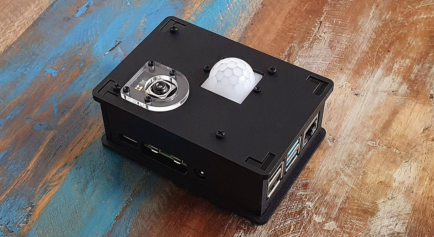
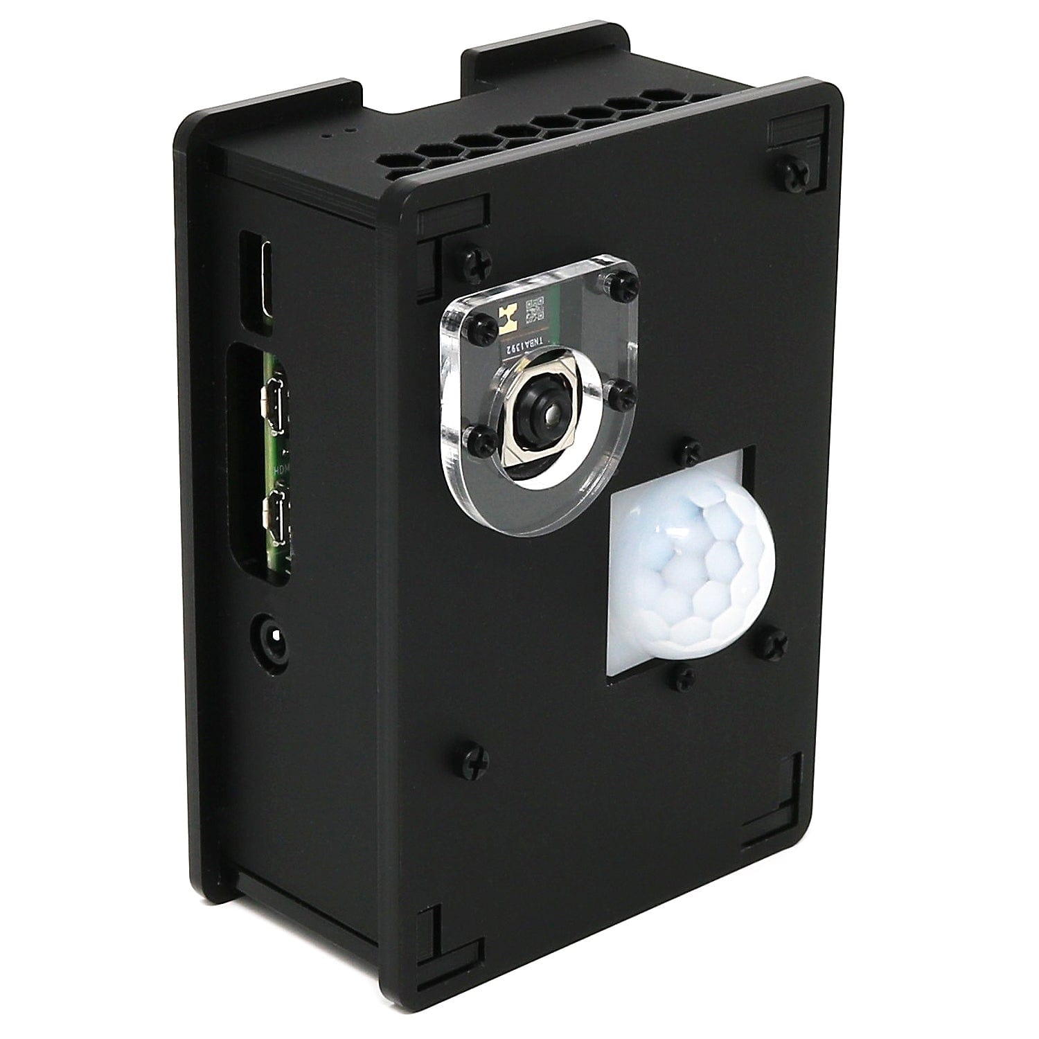
PIR Camera Case Assembly Instructions
This guide will show you how to assemble the PIR Camera Case for the Raspberry Pi 4. All you'll need is a simple cross-head screwdriver.
Step 1 – Snap the side panels out of their holders. Don't forget to peel off the protective plastic covering from all pieces:

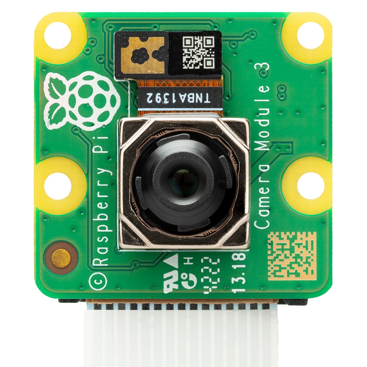
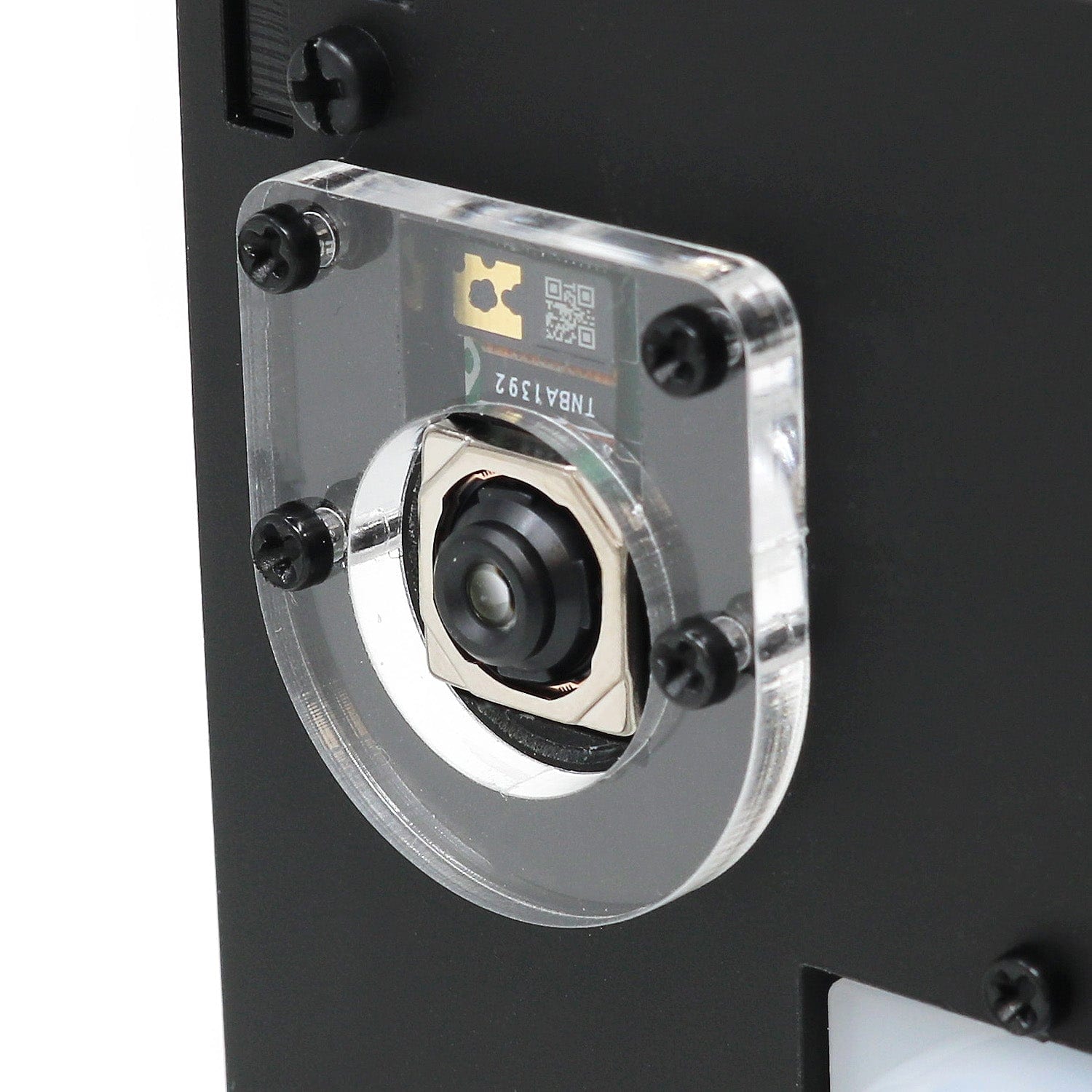
Step 2 – We'll get the fiddly part out of the way, secure the clear lens protector to the black front panel and your camera module using the long, thin M2 screws and four nuts (your lens protector may look different if purchased after 13/01/22).
Don't worry if you have left-overs, we included extras in your pack of parts:


Step 3 – Repeat again for the PIR sensor, this time using 2x M2 nuts as a spacer for the sensor board to sit on before you slide it on. Then secure the PIR with the remaining nuts.
We'd advise having the PIR header pins on the side closest to the camera cable.


Step 4 – Use 4x M2.5 screws to secure the smaller M/F standoffs to the base layer of the case. (Important! If you're mounting this case to a wall using one of our wall mounting brackets you'll want to quickly check out this guide)

Step 5 – Add your Raspberry Pi 4 and stack up the remaining standoffs. This case is extra-tall to accommodate the PIR sensor and camera cables.

Step 6 – Pit stop! Here's a handy photo to show you how the side panels will slot together. Each panel with have a slightly bumpy set of feet (from where we snapped them out of the panels), fear not - these go into the base so won't be seen.

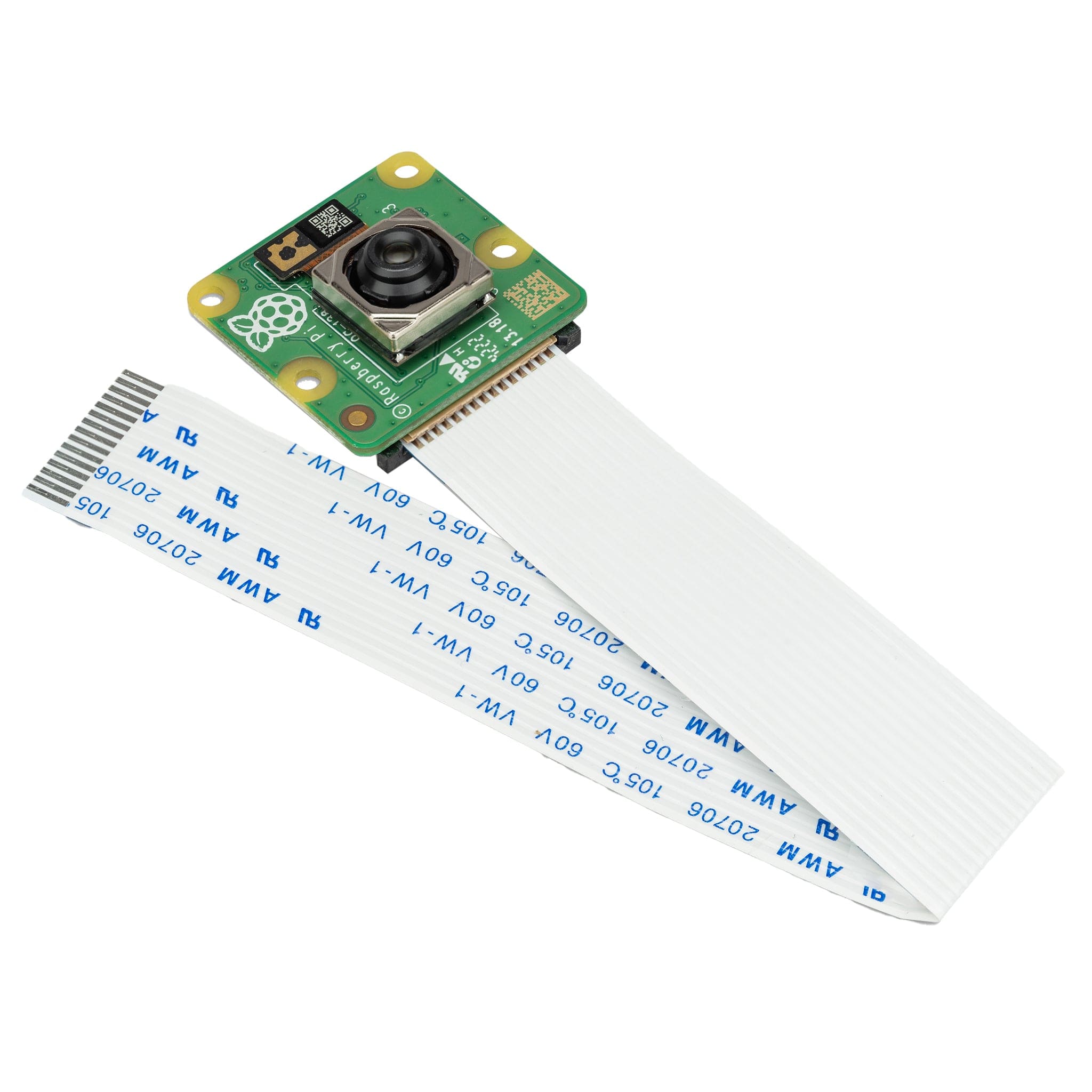
Step 7 – Now is a good time to connect your Raspberry Pi camera ribbon cable, make sure you have it connected the right way round.

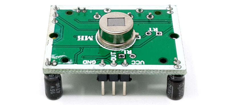
Step 8 – Now we'll connect the PIR sensor cables. Three cables are included in your kit, which need to connect your sensor to the Raspberry Pi's 5V, GND and GPIO 17 pins.
In the image below we've removed the cover from the PIR sensor to show you the pin connection labels when facing from the pin side (you may receive a green or a blue sensor - they work the same way).
These need to be connected as follows:
| PIR Pin | Raspberry Pi Pin |
| Left pin ("GND") | Physical pin 6 (GND pin) |
| Middle pin ("OUT") | Physical pin 11 (GPIO 17) |
| Right pin ("VCC") | Physical pin 4 (5V) |

Step 9 – Slot your side panels into place one by one. If the USB side panel is tight, just loosen the spacers a little to get the panel in place, then tighten again.

Step 10 – Now add the lid into place and secure with the remaining two screws

Job done! Now head over to our dedicated GitHub page for setup instructions and code examples.
5 comments
Agajan Torayev
Is this compatible with RPI 5? Or any cases for RPI5?
Is this compatible with RPI 5? Or any cases for RPI5?
Steve
Somehow got it all put together with much patience and perseverance. I love the look! Since the ‘raspi-’ package is being deprecated, would it be possible to put together a sister Github page dedicated to ‘libcamera’?
Somehow got it all put together with much patience and perseverance. I love the look! Since the ‘raspi-’ package is being deprecated, would it be possible to put together a sister Github page dedicated to ‘libcamera’?
Philip Rutter
I agree that the screws and nuts are difficult but found that if you use a finger tip to hold the nut against the flat piece with a hole that you are passing the screw through this keeps the nut at right angles to the screw and that makes it slightly easier, or at least possible. It still requires patience (lots of patience) and the ability to find a tiny nut on the floor when it has slipped out of your grasp!
I agree that the screws and nuts are difficult but found that if you use a finger tip to hold the nut against the flat piece with a hole that you are passing the screw through this keeps the nut at right angles to the screw and that makes it slightly easier, or at least possible. It still requires patience (lots of patience) and the ability to find a tiny nut on the floor when it has slipped out of your grasp!
Stephen
Hi,
Is it possible to include a POE module internally ?
Thanks
Hi,
Is it possible to include a POE module internally ?
Thanks
Paul Mead
Impossible to get the tiny nuts on the tiny screws!
Impossible to get the tiny nuts on the tiny screws!