

MicroPython Skill Builders - #8 OLED Display Graphics
Welcome to the eighth instalment of our MicroPython Skill Builders series by Tony Goodhew, aiming to improve your coding skills with MicroPython whilst introducing new components and coding techniques - using a Raspberry Pi Pico!
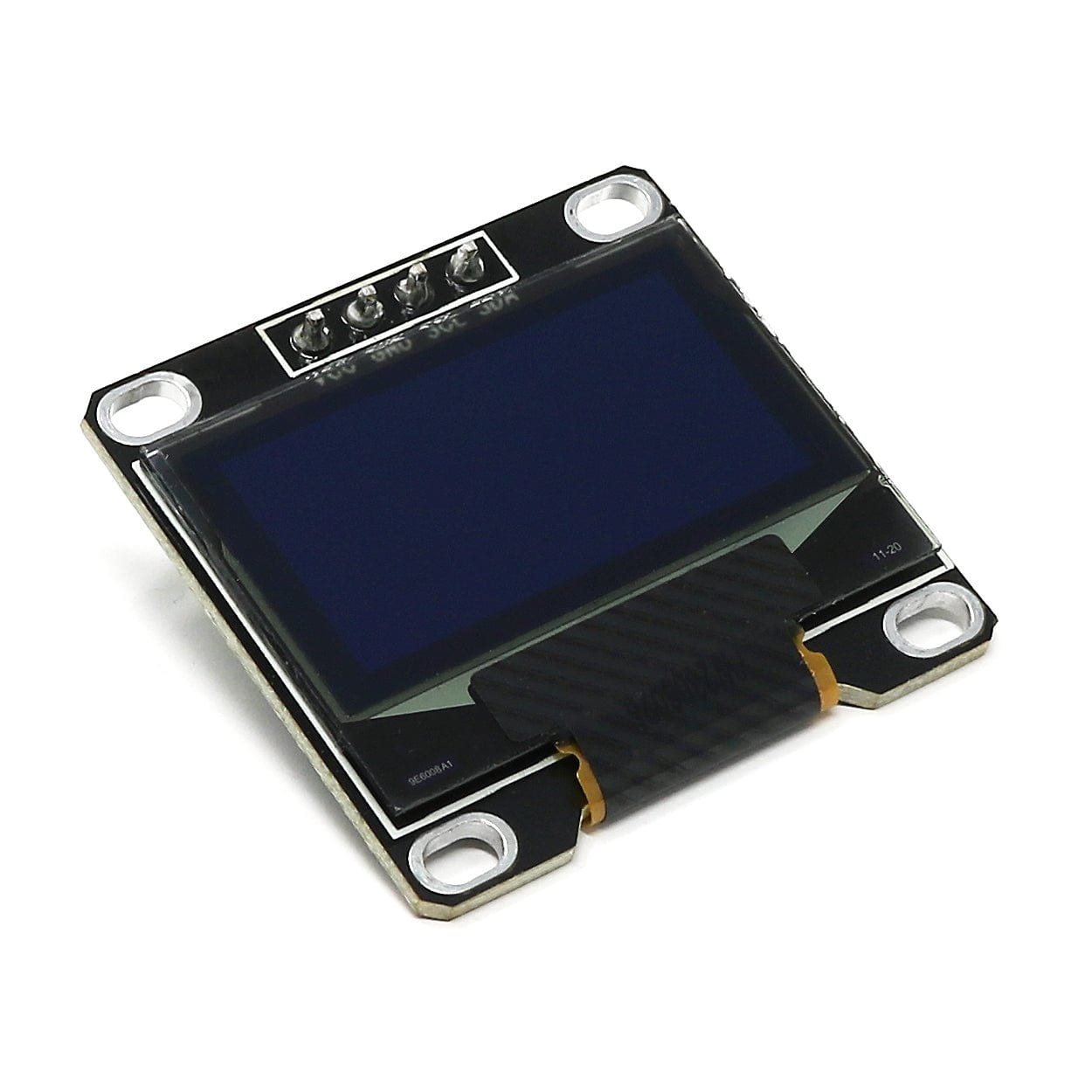
In the last Skill Builder we showed you how to use SPI OLED displays. This week we're covering I2C displays, specifically displaying graphics on them!
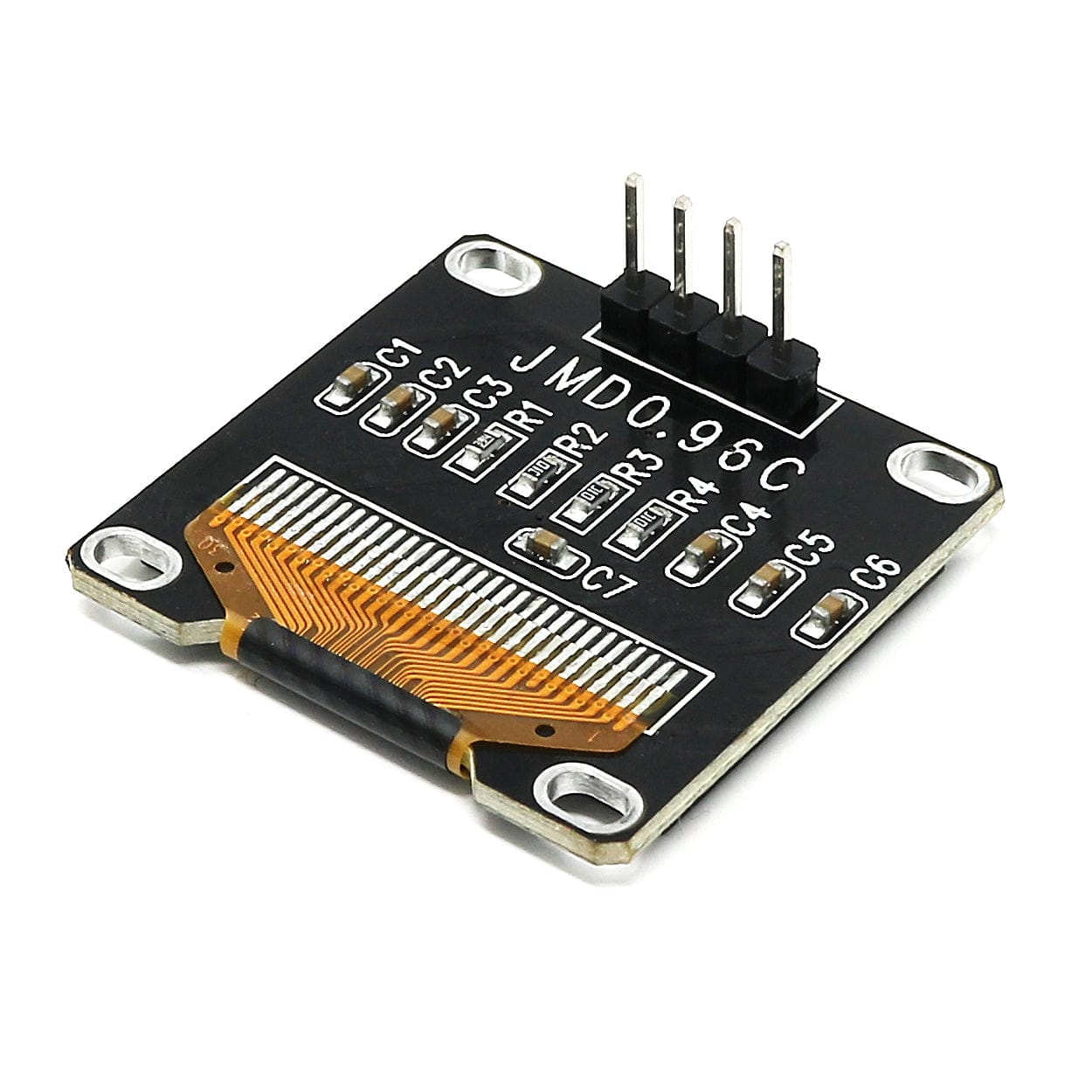
We now stock these very useful, inexpensive and easy to use mono 0.96” I2C OLED 128x64 pixel displays using the I2C (eye-squared-C) interface which only needs two GPIO pins for the data connection. In this tutorial will demonstrate how easy it is to get them working and explain how they can display both text and graphics.
The code we include also works perfectly with the SPI SSD1315 display introduced in our previous tutorial and with many SSD1306 displays from Waveshare and Adafruit which we stock.
What you will need
We assume that you have installed Thonny on your computer and set up your Raspberry Pi Pico with the most recent MicroPython firmware (UF2). If not, check out our Raspberry Pi Pico Getting Started Guide where this is covered in detail.
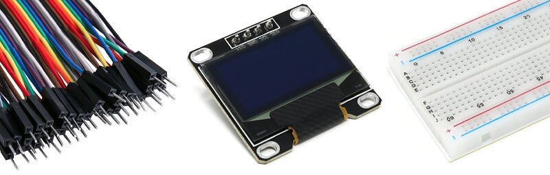
You will need:
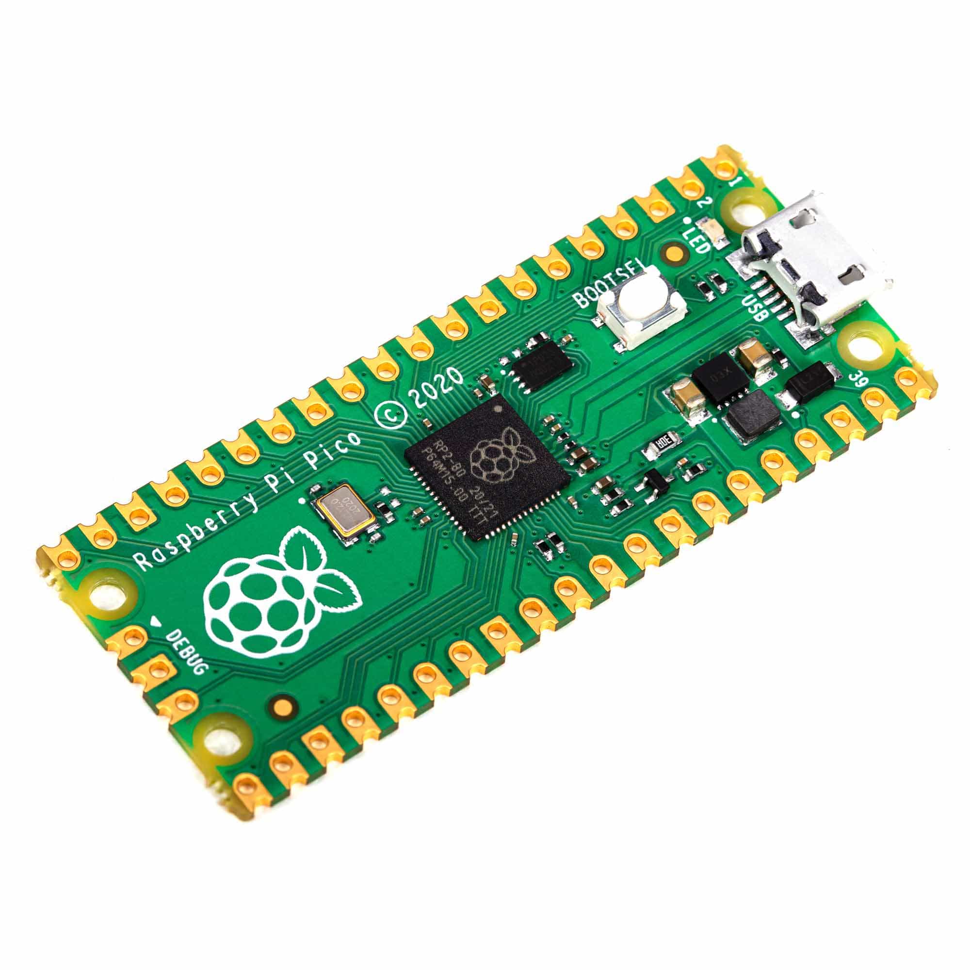
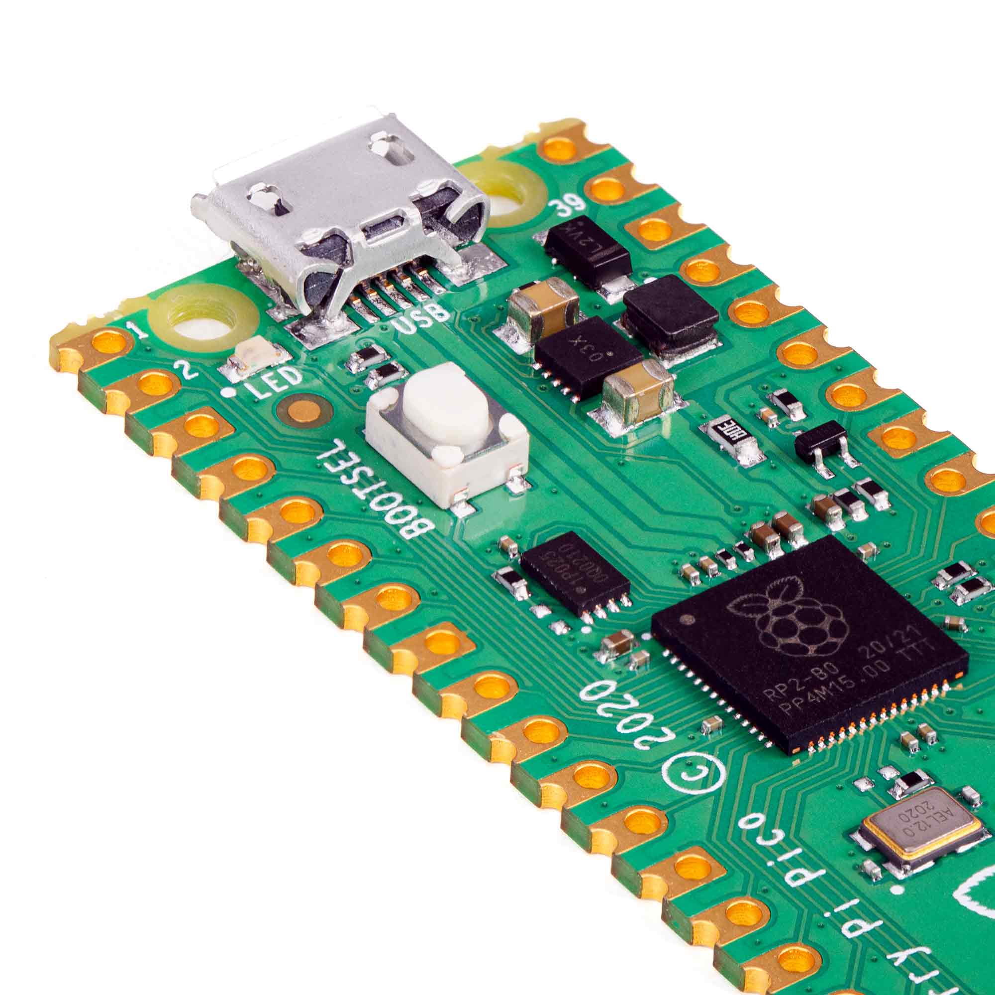
- Raspberry Pi Pico with header pins
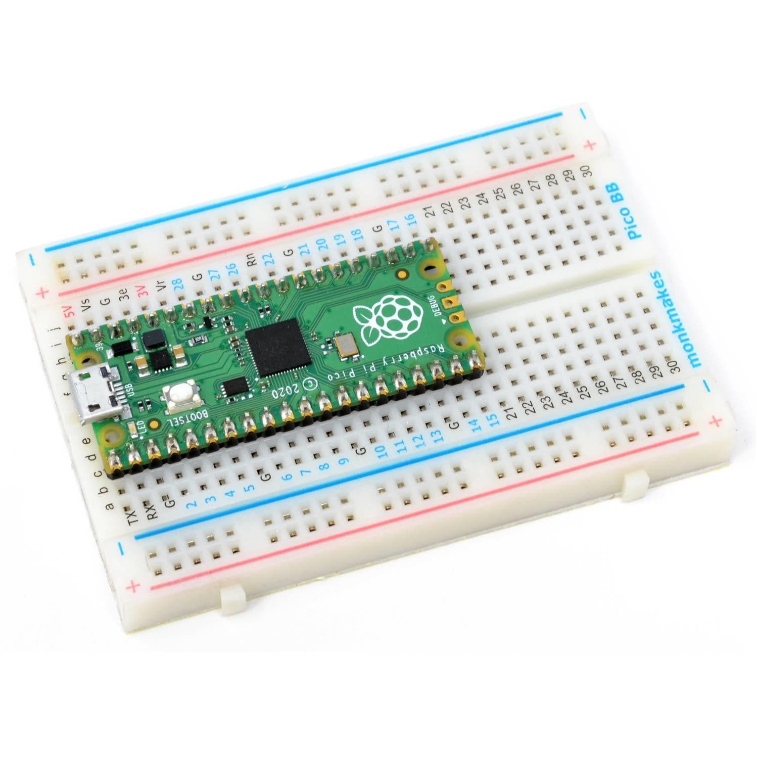
- A full-size breadboard
- Micro-USB cable (for power and programming the Pico)
- 0.96” I2C OLED 128x64 pixel display
- Jumper wires (male/male and male/female, mixed colours ideally)
- Optional - 10K Ohm potentiometer
The I2C Bus
The Inter-Integrated Circuit (I2C) bus is a two-wire serial interface originally developed by the Phillips Corporation in 1982.
The original definition used inappropriate language. We will use MAIN as the device supplying the CLOCK signal (SLC), a Pi Pico, and SUB-NODE for the other device, the display. The other signal, SERIAL DATA (SDA), can work in both directions but with the display we only send data from the Pico to the display.
The Pico has two I2C Bus Controllers – 0 and 1. All I2C devices have an address which is used to differentiate between several sub-nodes which could be connected in parallel to the same GPIO pins.
These displays usually have an address of 0x3C but some, possibly from Adafruit, use 0x3D. You can read more about the I2C Bus here.
Connecting the Display
The pins on the display are labelled and can be connected in many different places. We will use the Pico’s default I2C pins – GPIO 8 (SDA) and GPIO 9 (SCL) on bus controller 0.
VCC is connected to 3.3 volts and GND to a GND pin.
The potentiometer slider is connected ADC2 (GPIO 28) and its ends to the 3.3V and GND rails. The table shows the other possible positions:
| I2C | SDA | SCL |
| 0 | 0 | 1 |
| 1 | 2 | 3 |
| 0 | 4 | 5 |
| 1 | 6 | 7 |
| 0 | 8 | 9 |
| 1 | 10 | 11 |
| 0 | 12 | 13 |
| 1 | 14 | 15 |
| 0 | 16 | 17 |
| 1 | 18 | 19 |
| 0 | 20 | 21 |
| 1 | 26 | 27 |
Your circuit should look something like this (we used Fritzing to create this image):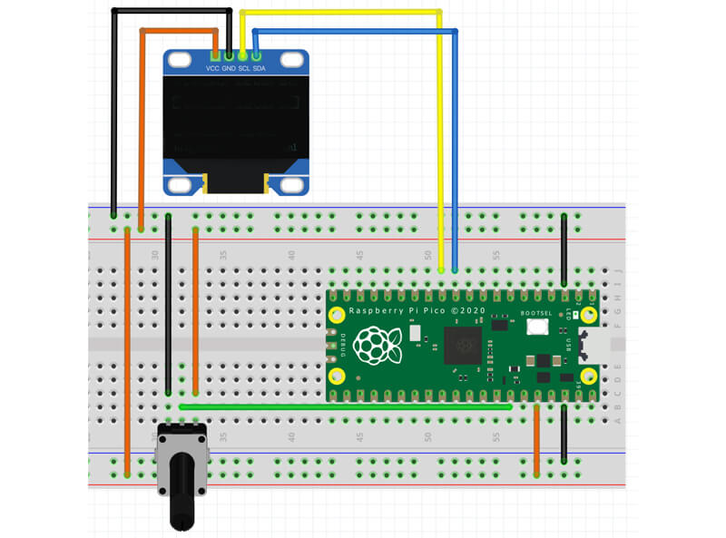
Install the code library
We need to install the micropython-ssd1306 library. This is the same library we used in Skill Builder #7.
If you have not already installed it, please, follow the link above to the instructions there to download and install the library.
How it works
The ssd1306 library sets up a small buffer in the Pico’s memory representing each pixel on the display’s screen. Each time we execute a display instruction, such as drawing a line or writing text to the display, we make changes to the data stored in the buffer.
Only when we execute the instruction oled.show() is the screen updated to make visible the changes we have made to the buffer. Leaving out this vital instruction is the most common error made by novice display users in their coding.
The ssd1306 library uses a powerful graphics library called framebuf. It makes available instructions to draw pixels, text, and lines, together with rectangles, ellipses and polygons both filled and in outline. You can see the full documentation here.
I2C Display Test Program
The following program checks that your I2C display is set up correctly and writes thePiHut.com on the screen.
Use this code for your I2C display at the top of the program for the rest of these examples. Include all the imports at the top of this code.
# Test the I2C connections
# Tony Goodhew - 1st Jan 2024 - for thepihut.com
import time
from machine import Pin, I2C, ADC
import ssd1306
import array # Needed for polygons

WIDTH  = 128         # oled display width
HEIGHT = 64          # oled display height

sda=machine.Pin(8)   # Data pin
scl=machine.Pin(9)   # Clock pin
i2c=machine.I2C(0,sda=sda, scl=scl, freq=400000) # Connection controller 0

oled = ssd1306.SSD1306_I2C(128, 64, i2c)         # Initialise ssd1306 display
# ======== ssd1306 set up for I2C ========

# ====== Universal code starts here ======
oled.fill(0)                      # Clear screen to BLACK
oled.text("ThePiHut.com",15,15,1) # Draw text in buffer - WHITE
oled.show()                       # Display the buffer
Graphics Routines in Framebuf
Text strings
The most useful routine is oled.text(string, x, y, c) which draws a text sting on the screen starting at position (x, y) in colour c.
The screen origin (0, 0) is at the top left and x increases to the right and y increases downwards.
The bottom right corner pixel is at (127, 63). This is a monochrome display with only two colours: white is 1 and black is 0. There is a built in 8x8 pixel font allowing 16 characters on a line.
The following procedure centres a text string on a line by setting the x value to half of the remaining space on the line:
# ====== Universal code starts here ======
def centre(msg, yy, cc):          # Procedure to centre text on a line
    space = WIDTH-(len(msg) * 8)  # Characters are 8 pixels wide
    gap = int(space/2)
    #    text(string, x, y, colour)
    oled.text(msg,gap,yy,cc)      # Write to buffer
Multiple lines of data
The next block of code sets a common delay time in seconds and draws several lines on the screen.
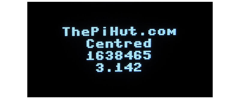
The first is positioned with (x, y) coordinates and the rest use the centring procedure. We see normal text, and two numbers, an integer and a float, which have to be converted to strings with str() before they can be displayed.
Here's the code:
delay = 3
# Waiting time in seconds

oled.fill(0) # Fill with Black
#        ( text string,   x,   y, colour)
oled.text("ThePiHut.com", 16, 10, 1) # White at (16,10)
centre("Centred",20,1)
integer = 1638465
centre(str(integer),30,1)
float = 3.142
centre(str(float),40,1)
oled.show()          # Send buffer to display
time.sleep(delay)
oled.fill(0)
Drawing pixels and horizonal/vertical lines
The next section demonstrates the drawing of pixels, horizonal and vertical lines.
![]()
Here's the code:
oled.text("pixels",5,20,1)
# oled.pixel(x,y,c)
oled.pixel(20,30,1) # (20,30)
oled.pixel(23,31,1) # (23,31)
oled.show()
time.sleep(delay)

oled.text("hline",0,0,1)
# oled.text(string,x,y,c)
oled.hline(5,15,100,1)
oled.show()
time.sleep(delay)

oled.text("vline",70,50,1)
# oled.vline(x,y,w,c)
oled.vline(120,5,55,1)
oled.show()
time.sleep(delay)
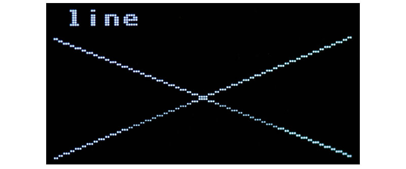
Crossing lines
The following code draws crossing lines.
Here's the code:
oled.fill(0)
oled.text("line",5,0,1)
# oled.line(x,y,x1,y1,c)
oled.line(0,12,127,63,1) # TL to BR
oled.line(127,12,0,63,1) # BL to TR
oled.show()
time.sleep(delay)
Multiple straight lines
Here we draw multiple straight lines using a loop to move the end points.
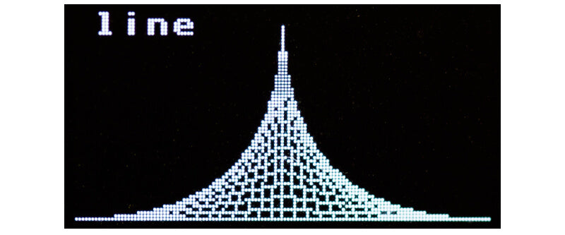
Here's the code:
oled.fill(0)
oled.text("line",5,0,1)
oled.hline(0,63,128,1)
for i in range(0,64,8): # Draws a spike
    oled.line(63,64-i,127-i,63,1)
    oled.line(63,64-i,i,63,1)
    oled.vline(63,64-i,i,1)
    oled.show()
    time.sleep(0.06)
oled.show()
time.sleep(delay)
Rectangles
This section demonstrates rectangles. We supply the coordinates of the top left corner, the width and the height. We can fill a rectangle by adding an extra value: f = True or 1 to fill the rectangle.
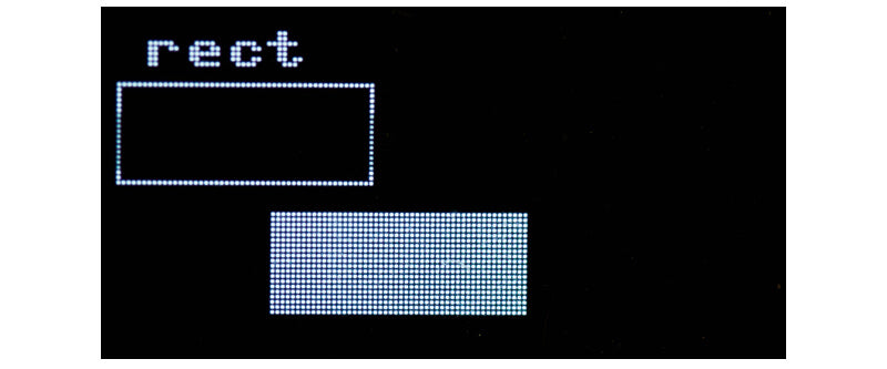
Here's the code:
oled.fill(0)
oled.text("rect",5,0,1)  # Rectangles
# oled.rect(x,y,w,h,c,[f])
oled.rect(0,10,50,20,1)       # Outine
oled.rect(30,35,50,20,1,True) # Filled: True = 1 and False = 0
oled.show()
time.sleep(delay)
Ellipse
The ellipse procedure allows us to draw ellipses and circles. (x ,y) is the centre, rx and ry are the radii, c the colour and f controls if it is filled. If rx is equal to ry we get a circle.
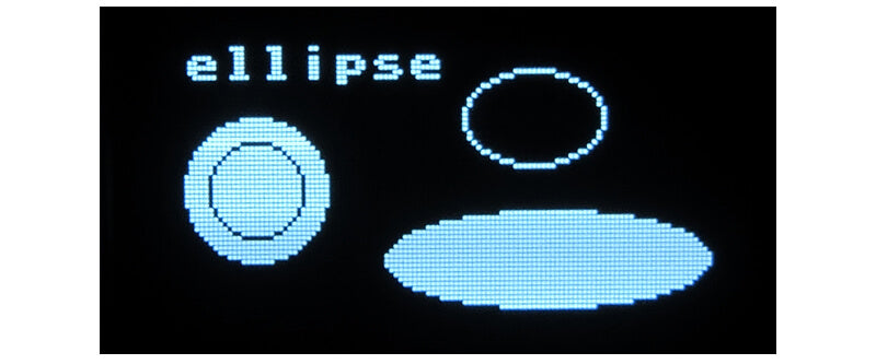
Here's the code:
oled.fill(0)
oled.text("ellipse",5,0,1) # Ellipses and Circles
# oled.ellipse(x,y,rx,ry,c,[f])
oled.ellipse(80,15,15,10,1)      # Outine
oled.ellipse(83,45,35,10,1,1)    # Filled
oled.ellipse(20,30,15,15,1,True) # Filled circle (rx = ry)
oled.ellipse(20,30,10,10,0)      # Outline circle (rx = ry)
oled.show()
time.sleep(delay)
Poly
The poly procedure is a bit more complicated but very powerful!
We first create an array (a special list) of integer coordinates for the corners of the required shape using the array library. C is the colour and f controls fill. Here x and y are normally set to zero and the polygon is drawn using the actual coordinates supplied. Non-zero values of x and y will offset the position of the polygon allowing it to be easily moved across the screen.

Here's the code:
oled.fill(0)
oled.text("poly",5,0,1) # Polygons - more complicated
# oled.poly((x, y, coords, c,[f])
# First create an integer array of the coordinates
hexagon = array.array('I',[30,10, 110,10, 126,30, 110,60, 30,60, 5,30]) # 6 pairs
# Draw the polygon
oled.poly(0,0, hexagon, 1, 1) # Filled hexagon
triangle = array.array('I', [30,12,120,30,33,55])
oled.poly(0,0, triangle, 0, True) # Filled
triangle = array.array('I', [37,18,100,30,45,44])
oled.poly(0,0, triangle, 1, ) # Outline
oled.show()
time.sleep(delay)
Things to try
- Paste the code segments above into Thonny below your display setup code to make a single program and run it on your system.
- Draw a triangle inside a quadrilateral, inside a pentagon inside a hexagon.
- Draw a small filled triangle near the top left of the screen. Using a loop move the triangle to the right and down the screen by changing the values of x and y each time it is redrawn. (Clear the screen with oled.fill(0) at the top of the loop.)
Bonus Program!
As space is limited, we provide this bonus code which illustrates animations and extended text facilities using a different font which can be used in four sizes.
The code is well commented and should be easy to follow. We include title sequences and sections which bounce a ball, display changing input from a potentiometer on a linear gauge and draw a cosine graph.
Download the code here: ssd1306 animations.py
Here's the video:
About the Author
This article was written by Tony Goodhew. Tony is a retired teacher of computing who starting writing code back in 1968 when it was called programming - he started with FORTRAN IV on an IBM 1130! An active Raspberry Pi community member, his main interests now are coding in MicroPython, travelling and photography.
6 comments
Jerry
I am trying to run micropython graphics programs with a Raspberry Pi Pico, using a 320 × 240 MSP2807 display and ili9341.
I am grateful for the limited success that I have had when running your:
“WS_2-0_320x240_MIN_9fbbe3d4-38ad-465b-ac02-19a324893935” program on my machine in micropython.
I have some questions about running this program in a more complete application. With your help can we work out a solution to my questions using e-mail?
Best wishes,
Jerry
Toby Szabo
Hi,
Where can I download the ssd1306 i2c library that supports line drawing?
I downloaded the library from https://github.com/stlehmann/micropython-ssd1306 because it was used on many sites, but it doesn’t have line drawing.
Thank you!
Hi,
Where can I download the ssd1306 i2c library that supports line drawing?
I downloaded the library from https://github.com/stlehmann/micropython-ssd1306 because it was used on many sites, but it doesn’t have line drawing.
Thank you!
Neil Hoskins
Solved. This tutorial assumes you’re following directly on from #7 and doesn’t remind us that to use i2c on this device you need to desolder part of the display and do some library tweaks as outlined here https://thepihut.com/blogs/raspberry-pi-tutorials/using-ssd1315-oleds-with-the-raspberry-pi-pico
Solved. This tutorial assumes you’re following directly on from #7 and doesn’t remind us that to use i2c on this device you need to desolder part of the display and do some library tweaks as outlined here https://thepihut.com/blogs/raspberry-pi-tutorials/using-ssd1315-oleds-with-the-raspberry-pi-pico
Neil Hoskins
I tried ditching the breadboard and reverted to the wiring that came in the box with the SSD1315 and connected red to 3V3(OUT), black to GND, blue (DIN on the display) to I2C0 SDA, and yellow (CLK on the display) to I2C0 SCL. That leaves orange, green, and white redundant. I left out the potentiometer as it doesn’t seem to be used in the first example.
Exact same errors.
Neil Hoskins
I have exactly the same as wizev
I have exactly the same as wizev
wizev
I was trying to do this but is not working and I was using the correct code I did all the correct wiring as you show but my screen is a bit different it says GND then VCC then SCK then SDA I got it working with the Arduino uno but I can’t do it with the pico it keeps showing this error message
Traceback (most recent call last):
File “”, line 15, in
File “ssd1306.py”, line 110, in init
File “ssd1306.py”, line 36, in init
File “ssd1306.py”, line 71, in init_display
File “ssd1306.py”, line 115, in write_cmd
OSError: [Errno 5] EIO
I am new to coding and not quite shaw what the issue is could you help me