
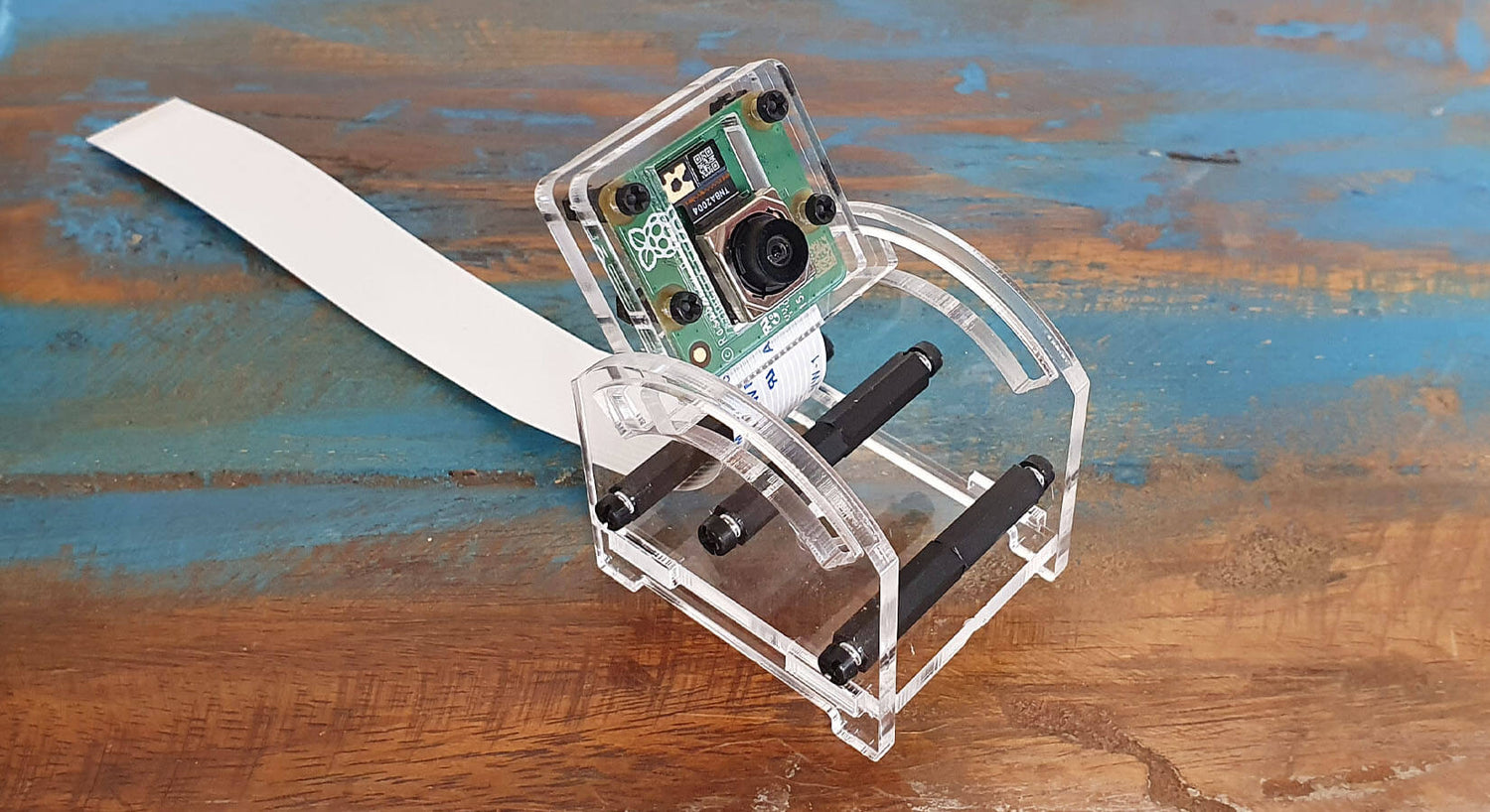
Adjustable Raspberry Pi Camera Mount Assembly Guide
This guide will show you how to assemble the Adjustable Raspberry Pi Camera Mount & Protector. All you'll need is a simple cross-head screwdriver.
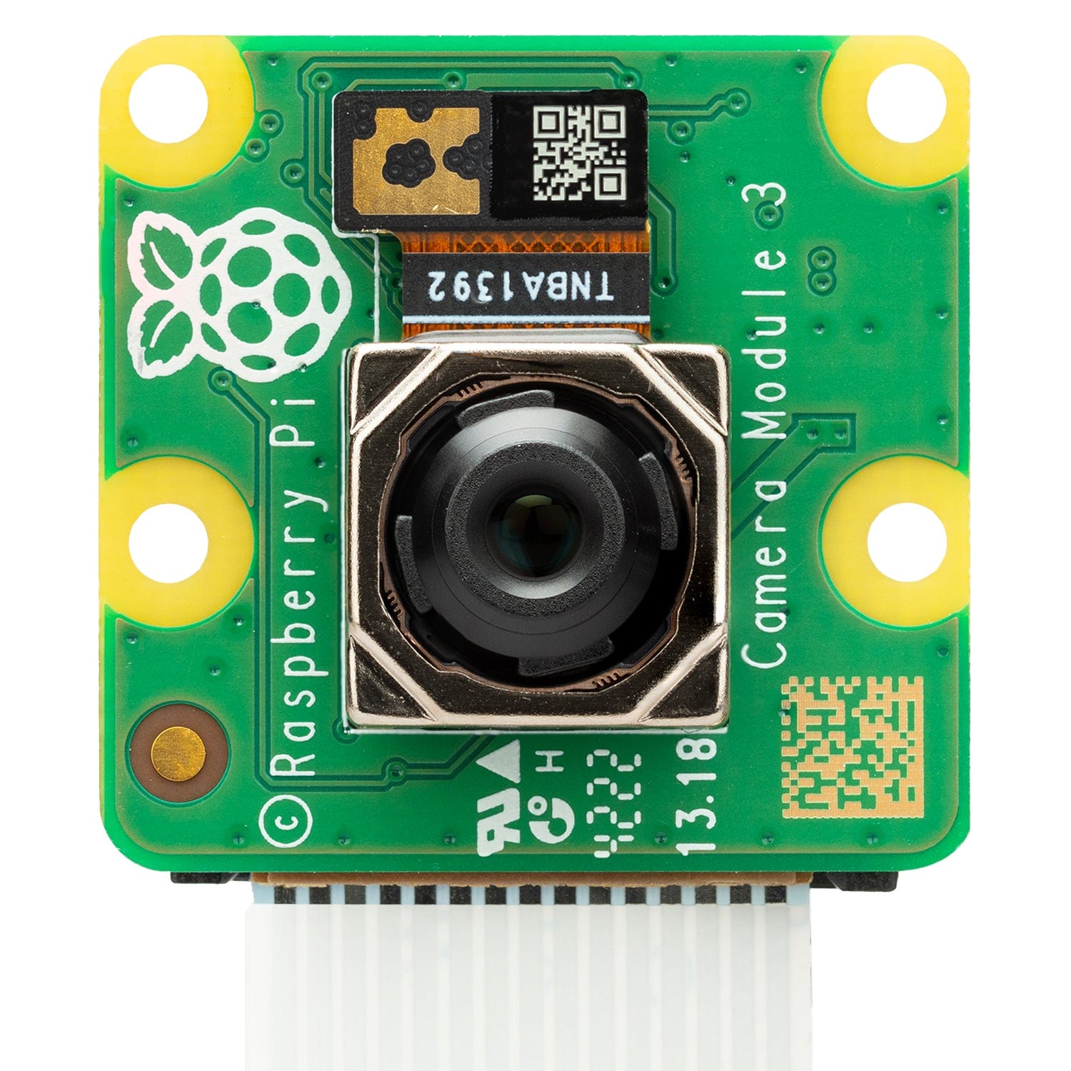
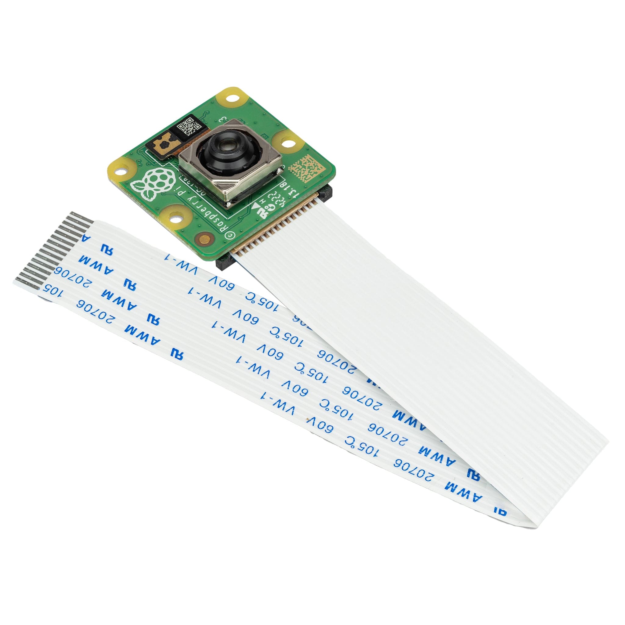
We recommend testing your camera module before fitting, to make sure the flex cable is connected properly. We also recommend undertaking this assembly on a tray or similar to avoid losing parts.
Step 1 – Snap the 5 panels out of their holders. Don't forget to peel off the protective plastic covering from all pieces:

Step 2 – Pass the four longer/thinner (M2) screws through the plastic camera panel (the one with the big rectangle hole in the middle):

Step 3 – Now for the fiddly bit, you need to secure the camera module to the panel with the included nuts - use two nuts per screw as this ensures the camera isn't squashed later on.
It's best to try to hold everything in your hands to avoid resting on the lens and causing damage. These nuts are small and a bit fiddly - just take your time. You may find it easier to remove the other screws and just do one at a time - whatever works best for you:

Step 4 – Add the other camera protector layer on top and secure into place with four nuts (one per screw). Don't worry if you have left-over nuts, we included extras in your pack of parts:

Step 5 – Now for the side panels. Screw the female to male standoffs on to one panels using three of the thicker (M2.5) screws:

Step 6 - Screw the remaining female to female standoffs on to the male ones like this:

Step 7 – Slot the bottom of the mount into the side panel:

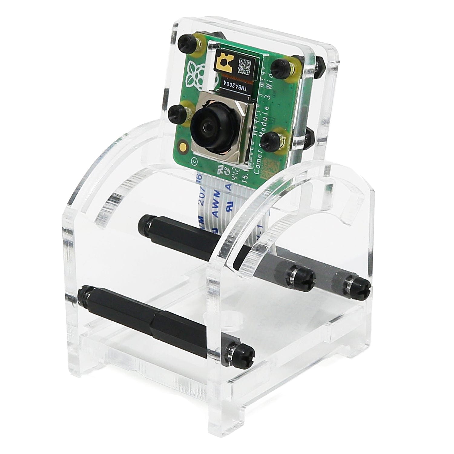
Step 8 – You need to do a few things at once here! Fit your camera part (that we made earlier) into the long groove whilst adding the other side panel.
One everything is in place, use the remaining screws to hold it all together. We recommend locking this into place with a single screw at first - you can add the remaining screws once the camera-holder is secured in place.
This is also a good time to get the camera cable where you want it (however you like):

Step 9 - Job done! Connect the camera to your Raspberry Pi and get cracking with libcamera!


14 comments
The Pi Hut
@carey – It doesn’t impact the Pi ports at all as it’s standalone. You just need to be able to get to your Raspberry Pi’s CSI port.
@carey – It doesn’t impact the Pi ports at all as it’s standalone. You just need to be able to get to your Raspberry Pi’s CSI port.
carey
does this external mount leave access to the micro hdmi and usbc power ports?
does this external mount leave access to the micro hdmi and usbc power ports?
Jack
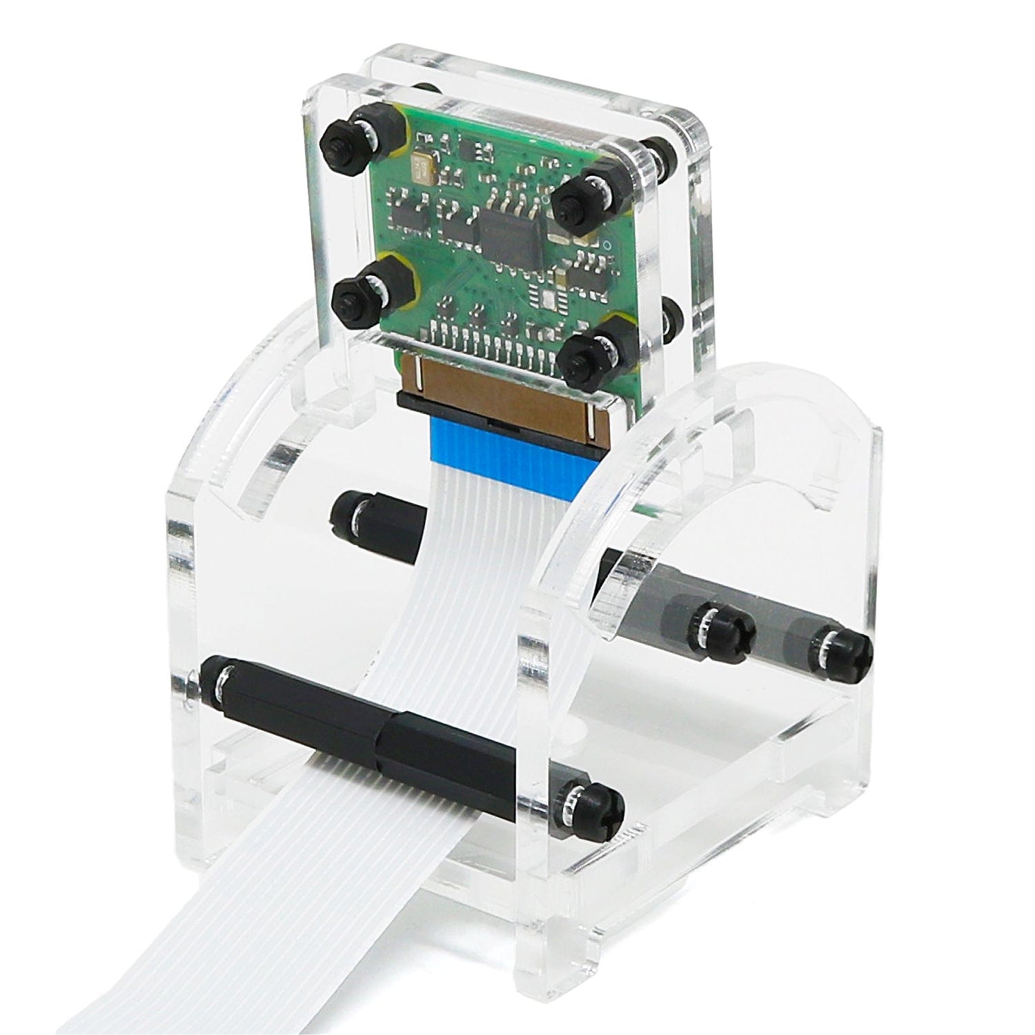
When assembling the camera for use with the Pi 5, the narrower ribbon cable needs to be used: the wide cable that comes fitted out of the box, is too wide to fit into the Pi 5.
I found this out after assembling the camera. This required a partial disassembly of the camera, followed by fitting the wide end of the spare ribbon cable into the camera, the correct way round, into the camera. Then it is possible to insert the ribbon cable (narrow end) into the Pi 5, ensuring that it is inserted the right way round.
Justin
Is this compatible with the new AI camera module? Thanks!
Is this compatible with the new AI camera module? Thanks!
Patrick
This works but it took the better part of an hour to assemble (V3 camera) because the bolts are so tiny it is extremely difficult to place and tighten them. I guess I’m happy with it but after assembling I think Im wondering ifa gorilla pod tripod type design that would be easier to assemble and allow vertical height adjustment wouldn’t be better.
It does look like friction will keep the camera in the same location; important for Timelapse. But the V3 camera cable is too short to allow much camera movement / placement anyway (15cm) so this is probably fine.This works but it took the better part of an hour to assemble (V3 camera) because the bolts are so tiny it is extremely difficult to place and tighten them. I guess I’m happy with it but after assembling I think Im wondering ifa gorilla pod tripod type design that would be easier to assemble and allow vertical height adjustment wouldn’t be better.
It does look like friction will keep the camera in the same location; important for Timelapse. But the V3 camera cable is too short to allow much camera movement / placement anyway (15cm) so this is probably fine.High Pi
@Andy I couldn’t agree more about creating a 3D print project. If the designer wants to make a few dollars per download of the STL, upload the file to cults3d and charge ~$4 for it. Win-win and we don’t have to deal with shipping.
@Andy I couldn’t agree more about creating a 3D print project. If the designer wants to make a few dollars per download of the STL, upload the file to cults3d and charge ~$4 for it. Win-win and we don’t have to deal with shipping.
Rob
OK, the nuts are a little fiddly but nothing crazy, just do one bolt at a time, put one nut on a mouse mat to keep it flat and then press down on the bolt as you screw it in. Hold the nut and screw it in a bit more, repeat with the second nut then just hold them both and screw them all the way down. Took less than 5 mins to put together including routing the cable into the raspberry pi5 case above the ethernet port. Great little product :D
OK, the nuts are a little fiddly but nothing crazy, just do one bolt at a time, put one nut on a mouse mat to keep it flat and then press down on the bolt as you screw it in. Hold the nut and screw it in a bit more, repeat with the second nut then just hold them both and screw them all the way down. Took less than 5 mins to put together including routing the cable into the raspberry pi5 case above the ethernet port. Great little product :D
The Pi Hut
@Toby – Sounds like you may have fitted the camera upside down with the ribbon cable coming out of the top (either that or your camera commands are rotating the image)
@Toby – Sounds like you may have fitted the camera upside down with the ribbon cable coming out of the top (either that or your camera commands are rotating the image)
Toby
Don’t know if it’s me, but this hold the camera (v2 anyway) upside down?!
Don’t know if it’s me, but this hold the camera (v2 anyway) upside down?!
John Harrison
I found it difficult to assemble with my ancient hand, once assembled it works fine. Quite difficult to replace the ribbon cable when I swapped it from a pi 4 to a pi zero.
I found it difficult to assemble with my ancient hand, once assembled it works fine. Quite difficult to replace the ribbon cable when I swapped it from a pi 4 to a pi zero.
The Pi Hut
@Sean – Thanks for the feedback. As per the earlier comments, we’re going to find some M2 standoffs (or similar) to replace some of the fiddly nuts. We may even look at a laser-cut spacer instead.
Re static, it’s really not as big of an issue as some make it out to be. The Raspberry Pi (and accessories such as the camera) were designed to be handled by children and upwards, which usually means mishandling of every type! Despite this, boards in educational arenas continue to work just fine – because it really isn’t the board killer people make it out to be (yes static damage is still a thing, but it’s very rare).
Sean
The assembly of the camera holder itself is very, very time-consuming; I cannot see how this design was let loose on the buying public. Bearing in mind past experience with the vulnerability to static of Pi camera modules, it’s asking for trouble as well – as being a pain – if your fingers are bigger than a child’s. What should take less than five minutes took much longer, for two reasons: 1. the nuts are very small, and 2. plastic nuts and bolts are the devil’s inventions. There should be spacers instead of the nuts between the two layers of acrylic.
The assembly of the camera holder itself is very, very time-consuming; I cannot see how this design was let loose on the buying public. Bearing in mind past experience with the vulnerability to static of Pi camera modules, it’s asking for trouble as well – as being a pain – if your fingers are bigger than a child’s. What should take less than five minutes took much longer, for two reasons: 1. the nuts are very small, and 2. plastic nuts and bolts are the devil’s inventions. There should be spacers instead of the nuts between the two layers of acrylic.
The Pi Hut
@Andy The little nuts and bolts can get fiddy but we’re limited by the M2 holes in the camera module (we’d love Raspberry Pi to move to M2.5 holes, but the board would probably have to be larger to accommodate that) and our manufacturing process (we use a laser cutter not a CNC machine, so milling isn’t an option currently). The simple manufacturing process helps keep the cost down though. Thanks for the feedback, if we can find some slim M2 spacers to replace the doubled-up nuts, we’ll move to them to help make things a bit easier.
@Andy The little nuts and bolts can get fiddy but we’re limited by the M2 holes in the camera module (we’d love Raspberry Pi to move to M2.5 holes, but the board would probably have to be larger to accommodate that) and our manufacturing process (we use a laser cutter not a CNC machine, so milling isn’t an option currently). The simple manufacturing process helps keep the cost down though. Thanks for the feedback, if we can find some slim M2 spacers to replace the doubled-up nuts, we’ll move to them to help make things a bit easier.
Andy
For the Camera Module 3
One part of this design is terrible. That is the part that holds to camera module itself. The module is sandwiched between two perspex panels, and held in place by 4 very small bolts and 12 nuts. These are very very fiddly to fit, and the requirement to need two nuts stacked to make a spacer makes things even more fiddly. It’s just about impossible to spin the nuts onto the bolts without dropping them. Work over a tray to catch them!
A simple milled slot in a thicker plastic backplate would have done a much better job.
A good candidate for a 3D printer projet.
Andy