
Turning on an LED with your Raspberry Pi's GPIO Pins
One of the biggest selling points of the Raspberry Pi is the GPIO, or General Purpose Input/Output pins. They are the little pins sticking out of the circuit board which allow you to plug various devices into your Raspberry Pi - anything from sensors to displays. With a little programming, you can then control them or detect what they are doing.
In this tutorial we are going to show you how to light an LED with these GPIO pins - a nice simple first project for any Raspberry Pi owner!
What you will need
In addition to a Raspberry Pi running Raspberry Pi OS, you will need:
- A Breadboard
- An LED
- A 330 ohm resistor
- 2x Male to Female jumper wires
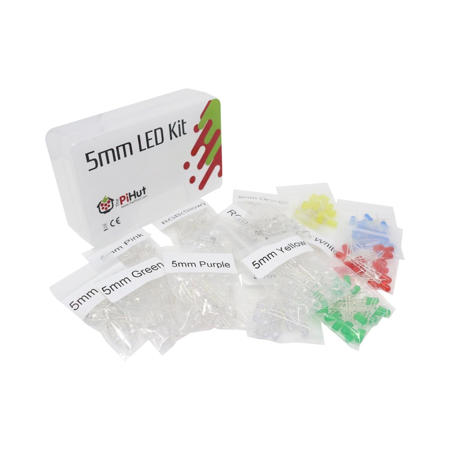
You can get all of these items, and more, in our CamJam EduKit, which teaches you more about LEDs, buzzers and switches, and includes all the hardware and eight well-written worksheets about using the GPIO pins on your Raspberry Pi.
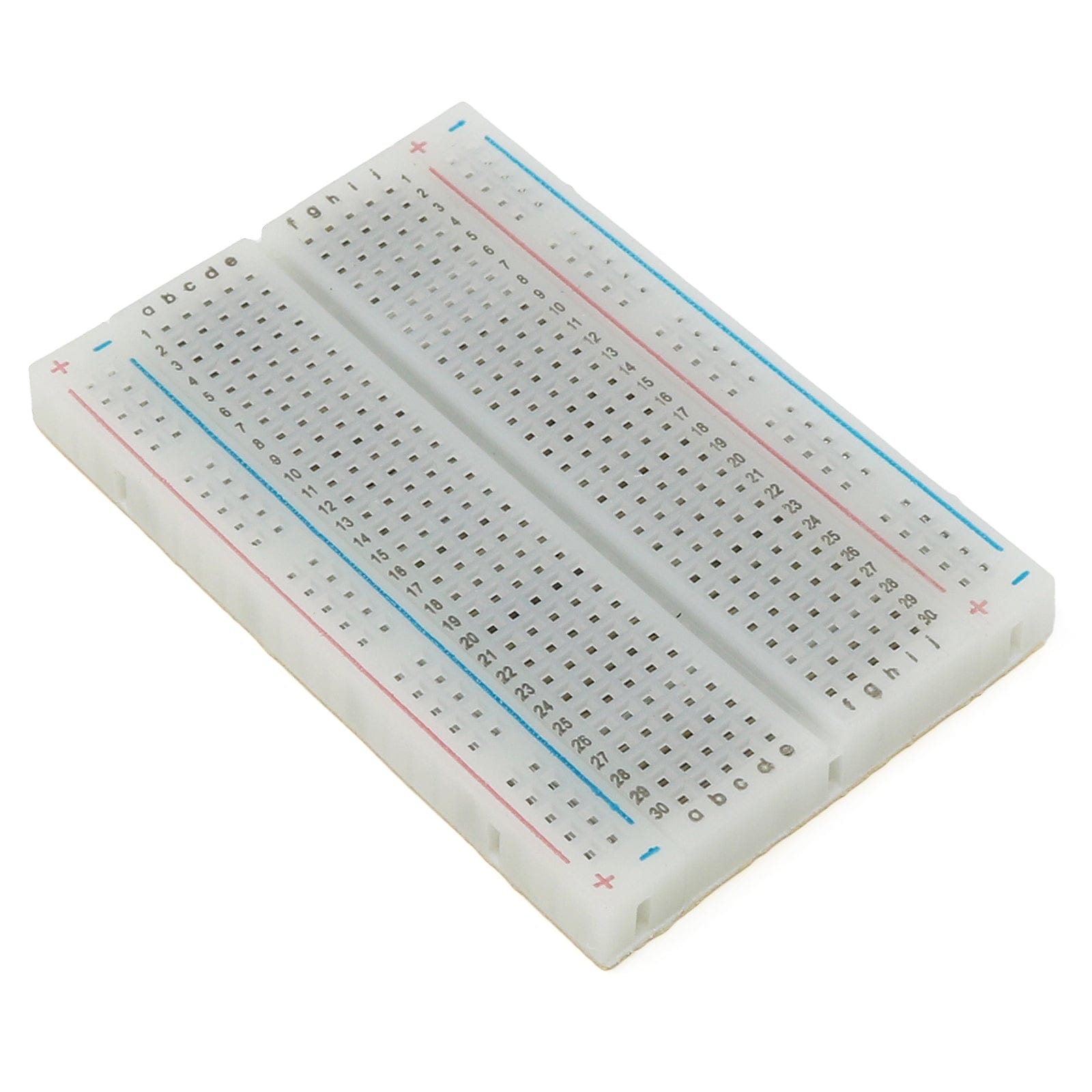
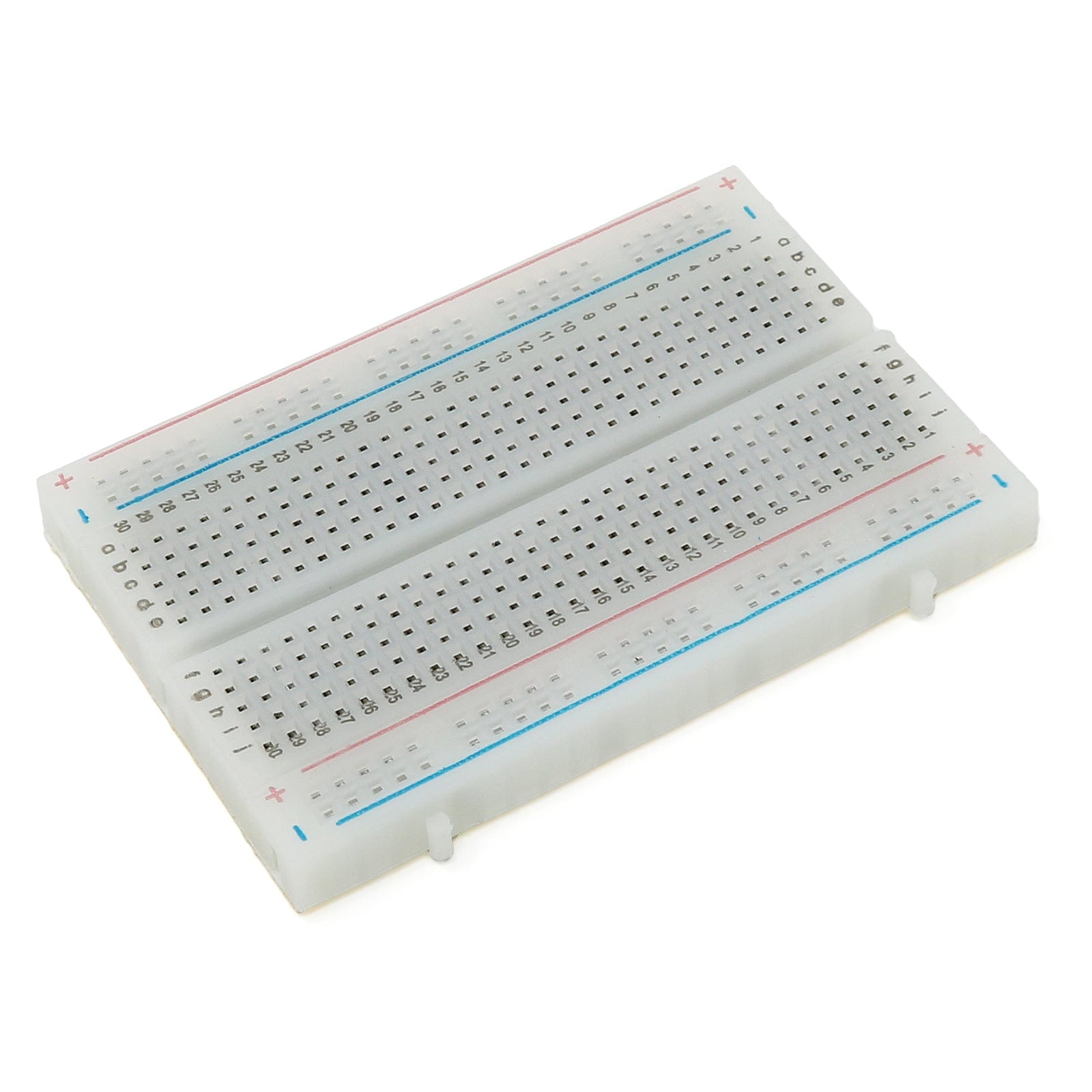
The Breadboard
The breadboard is a convenient way to connect electronic components to each other without having to solder them together.
They are often used to test ("prototype") a circuit design before making a final version of a project, whether that be soldering wires together or creating a Printed Circuit Board (PCB).
The holes on the breadboard are connected as follows:

With the breadboard in the CamJam EduKit, the top row of holes are all connected together, marked with a red line. And so are the second row of holes, marked with a blue line. The same goes for the matching two blue/red rows of holes at the bottom of the breadboard.
In the middle, the columns of holes are connected together with a break in the middle (which comes in handy if you straddle a chip or similar component across the two sides, allowing you to connect to both sides of a chip with wires, without the chip's legs connecting together)
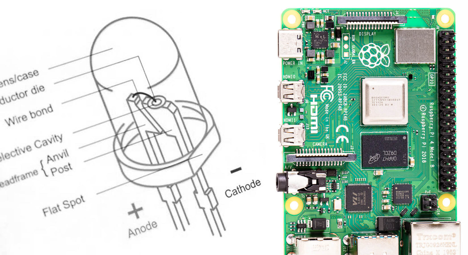
The LED
 When you pick up the LED, you will notice that one leg is longer than the other.
The longer leg (known as the ‘anode’), is always connected to the positive supply of the circuit. The shorter leg (known as the ‘cathode’) is connected to the negative side of the power supply, known as ‘ground’.
LED stands for Light Emitting Diode, and glows when electricity (current) is passed through it.
LEDs will only work if power is supplied the correct way round (i.e. if the ‘polarity’ is correct). You will not break the LEDs if you connect them the wrong way round, they will just not light. If you find that they do not light in your circuit, it may be because they have been connected the wrong way round.
The Resistor
![]() You must ALWAYS use resistors to connect LEDs up to the GPIO pins of the Raspberry Pi. The Raspberry Pi GPIO pins can only supply a small current (about 60mA). The LEDs will want to draw more, and if allowed to they may damage your Raspberry Pi or the pins used. Therefore adding resistors to the circuit will ensure that only this small amount of current will flow.
You must ALWAYS use resistors to connect LEDs up to the GPIO pins of the Raspberry Pi. The Raspberry Pi GPIO pins can only supply a small current (about 60mA). The LEDs will want to draw more, and if allowed to they may damage your Raspberry Pi or the pins used. Therefore adding resistors to the circuit will ensure that only this small amount of current will flow.
Resistors are a way of limiting the amount of electricity going through a circuit; specifically, they limit the amount of ‘current’ that is allowed to flow. The measure of resistance is called the Ohm (Ω), and the larger the resistance, the more it limits the current. The value of a resistor is marked with coloured bands along the length of the resistor body.
You will be using a 330Ω resistor. You can identify the 330Ω resistors by the colour bands along the body. The colour coding will depend on how many bands are on the resistors supplied:
- If there are four colour bands, they will be Orange, Orange, Brown, and then Gold.
- If there are five bands, then the colours will be Orange, Orange, Black, Black, Brown.
It does not matter which way round you connect the resistors. Current flows in both ways through them.
Jumper Wires
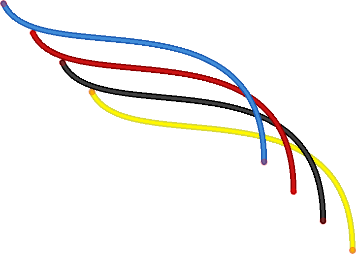 Jumper wires are used on breadboards to ‘jump’ from one connection to another. The ones you will be using in this circuit have different connectors on each end. The end with the ‘pin’ will go into the Breadboard. The end with the piece of plastic with a hole in it will go onto the Raspberry Pi’s GPIO pins.
The Raspberry Pi GPIO Pins
GPIO stands for General Purpose Input Output. It's a way the Raspberry Pi can control and monitor the outside world by being connected to electronic circuits.
The Raspberry Pi is able to control LEDs, turning them on or off, or motors, or many other things using these pins (this is known as an 'output'). It is also able to detect whether things like a switch has been pressed, or temperature, light and more (this is know an an 'input').
In the CamJam EduKit you will learn how to control LEDs and a buzzer, and detect when a button has been pressed. The diagram below left shows the pin layout for the older 26-pin Raspberry Pi Models which are no longer sold. The latest 40-pin Raspberry Pi’s share the same layout of pins for the top 13 rows as the old model.

Building the Circuit
The circuit consists of a power supply (the Raspberry Pi), an LED that lights when the power is applied, and a resistor to limit the current that can flow through the circuit:
- You will be using one of the ‘ground’ (GND) pins to act like the ‘negative’ or 0 volt ends of a battery.
- The ‘positive’ end of the battery will be provided by a GPIO pin. Here we will be using pin GPIO18 (which is physical pin 12).
- When these pins are ‘taken high’, which means it outputs 3.3 volts, the LED will light.

You should turn your Raspberry Pi off for the next bit, just in case you accidentally short something out.
- Use one of the jumper wires to connect a ground pin to the rail, marked with blue, on the breadboard. The female end goes on the Raspberry Pi's pin, and the male end goes into a hole on the breadboard.
- Then connect the resistor from the same row on the breadboard to a column on the breadboard, as shown above.
- Next, push the LEDs legs into the breadboard, with the long leg (with the kink) on the right.
- Lastly, complete the circuit by connecting the right hand leg of the LED to GPIO18. This is shown here with the blue wire.
The Code
You are now ready to write some code to switch the LED on. Turn on your Raspberry Pi and open the terminal window.
Create a new text file “LED.py” by typing the following:
nano LED.py
Type or copy over the following code:
import RPi.GPIO as GPIO
import time
GPIO.setmode(GPIO.BCM)
GPIO.setwarnings(False)
GPIO.setup(18,GPIO.OUT)
print "LED on"
GPIO.output(18,GPIO.HIGH)
time.sleep(1)
print "LED off"
GPIO.output(18,GPIO.LOW)
Once you have added all the code and checked it, save and exit the text editor with “Ctrl + x” then “y” then “enter”.
Running the Code
To run this code type:
sudo python LED.py
You will see the LED turn on for a second and then turn off.
If your code does not run and an error is reported, edit the code again using nano LED.py.
Explanation
So, what is happening in the code? Let’s go through it a line at a time:
import RPi.GPIO as GPIO
The first line tells the Python interpreter (the thing that runs the Python code) that it will be using a ‘library’ that will tell it how to work with the Raspberry Pi’s GPIO pins. A ‘library’ gives a programming language extra commands that can be used to do something different that it previously did not know how to do. This is like adding a new channel to your TV so you can watch something different.
import time
Imports the Time library so that we can pause the script later on.
GPIO.setmode(GPIO.BCM)
Each pin on the Raspberry Pi has several different names, so you need to tell the program which naming convention is to be used.
print "LED on"
This line prints some information to the terminal.
GPIO.output(18,GPIO.HIGH)
This turns the GPIO pin ‘on’. What this actually means is that the pin is made to provide power of 3.3volts. This is enough to turn the LED in our circuit on.
time.sleep(1)
Pauses the Python program for 1 second
print "LED off"
This line prints some information to the terminal.
GPIO.output(18,GPIO.LOW)
This turns the GPIO pin ‘off’, meaning that the pin is no longer supplying any power.
And that's it! You are now able to turn an LED on and off.
We used Fritzing to create the breadboard wiring diagram images for this page.

6 comments
Himanshubhusan Rath
Very much helpful and detailed tutorial. It needs little correction though. The print statement should have parenthesis.
Very much helpful and detailed tutorial. It needs little correction though. The print statement should have parenthesis.
Ean
I had to enter parenthesis in the print commands.
Print (“LED on”)
I had to enter parenthesis in the print commands.
Print (“LED on”)
eli
will it work for a pi 4
will it work for a pi 4
Matt
Big Happy Face as I finally mde this work and proud to have done it :)
Big Happy Face as I finally mde this work and proud to have done it :)
Gary
I used a Pi 2 and it worked but I needed to get the correct pin identified from a GPIO diagram for Pi 2. This tutorial is for Pi 3 or 4, so just be aware.
I used a Pi 2 and it worked but I needed to get the correct pin identified from a GPIO diagram for Pi 2. This tutorial is for Pi 3 or 4, so just be aware.
Tannar
I have looked at dozens of tutorials and none worked other than this one so thanks! If anyone else reading this with a zero 2 w this should work as it worked for me and that is what i am using
I have looked at dozens of tutorials and none worked other than this one so thanks! If anyone else reading this with a zero 2 w this should work as it worked for me and that is what i am using