Magnetic Encoder Pair Kit for Extended Back Shaft Micro Metal Gearmotors
Price:
Sale price
£8.70
Stock:
Quantity:
 Skip to content
Login / Signup
Cart
Your cart is empty


Add quadrature encoders to your micro metal gearmotors (extended back shaft version required) with this kit that uses a magnetic disc and Hall effect sensors to provide 12 counts per revolution of the motor shaft.
The sensors operate from 2.7V to 18V and provide digital outputs that can be connected directly to a microcontroller or other digital circuit.
These encoders have their pins arranged as through-holes on a 2mm pitch, and wires or 2mm-pitch connectors must be soldered in to use them.
Note: This item will not work on Micro Metal Gearmotors that don't have an extended rear shaft (we'll have these in the store soon!).
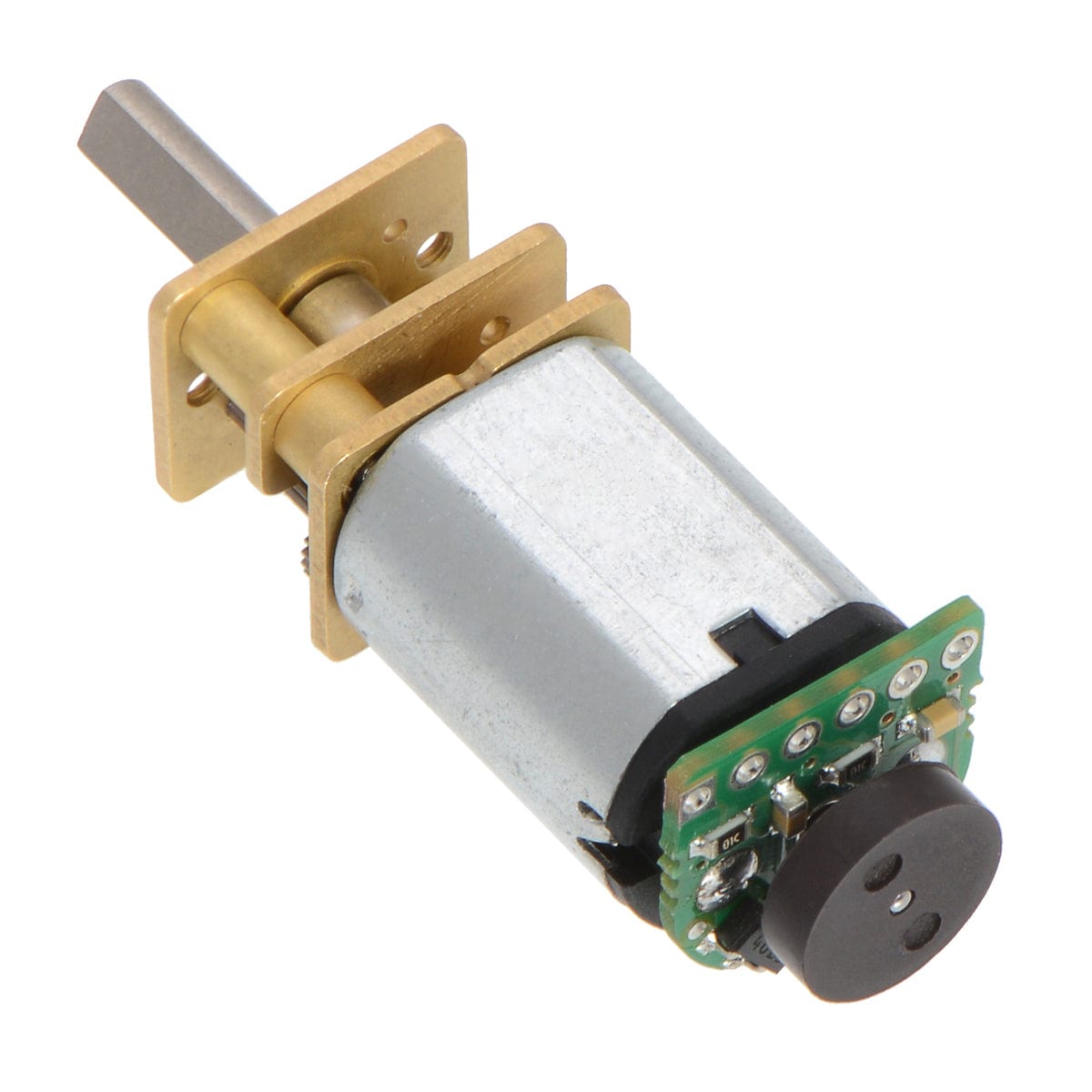
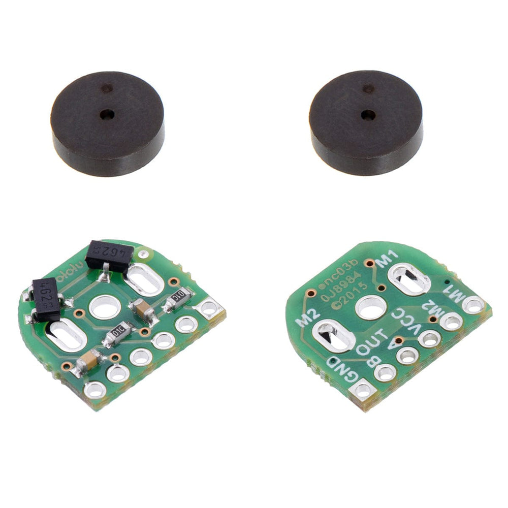
This Polulu kit includes two dual-channel Hall effect sensor boards and two 6-pole magnetic discs that can be used to add quadrature encoding to two micro metal gearmotors with extended back shafts (motors are not included with this kit). The encoder board senses the rotation of the magnetic disc and provides a resolution of 12 counts per revolution of the motor shaft when counting both edges of both channels. To compute the counts per revolution of the gearbox output shaft, multiply the gear ratio by 12.
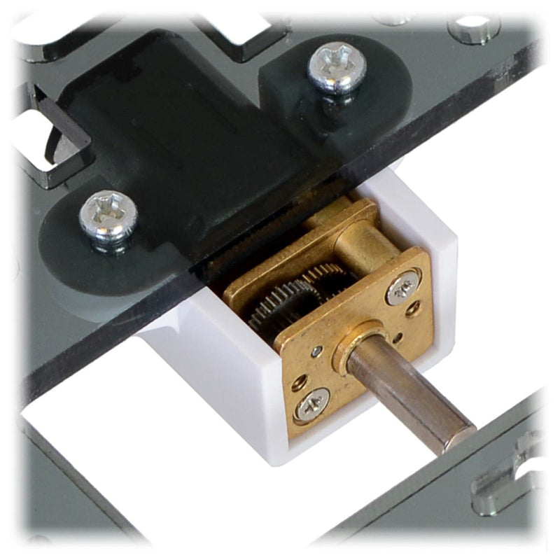
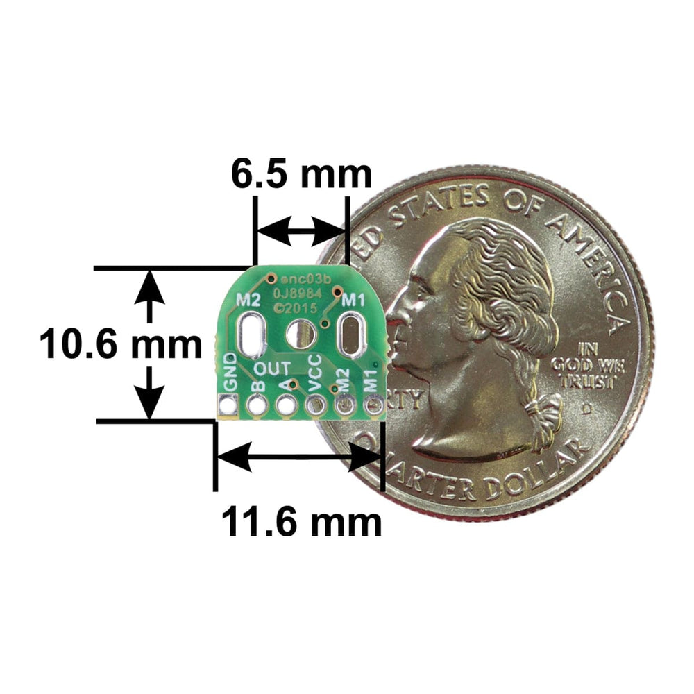
This compact encoder solution fits within the 12 mm × 10 mm cross-section of the motors on three of the four sides, and it only extends 0.6 mm past the edge of the fourth side (note: if you need it to be flush with that last side, you can carefully grind the board down a little and solder to the remaining half-holes). The assembly does not extend past the end of the extended motor shaft, which protrudes 5 mm beyond the plastic end cap on the back of the motor.
Note: This sensor system is intended for users comfortable with the physical encoder installation. It only works with micro metal gearmotors that have extended back shafts.
Motors and pin headers not included
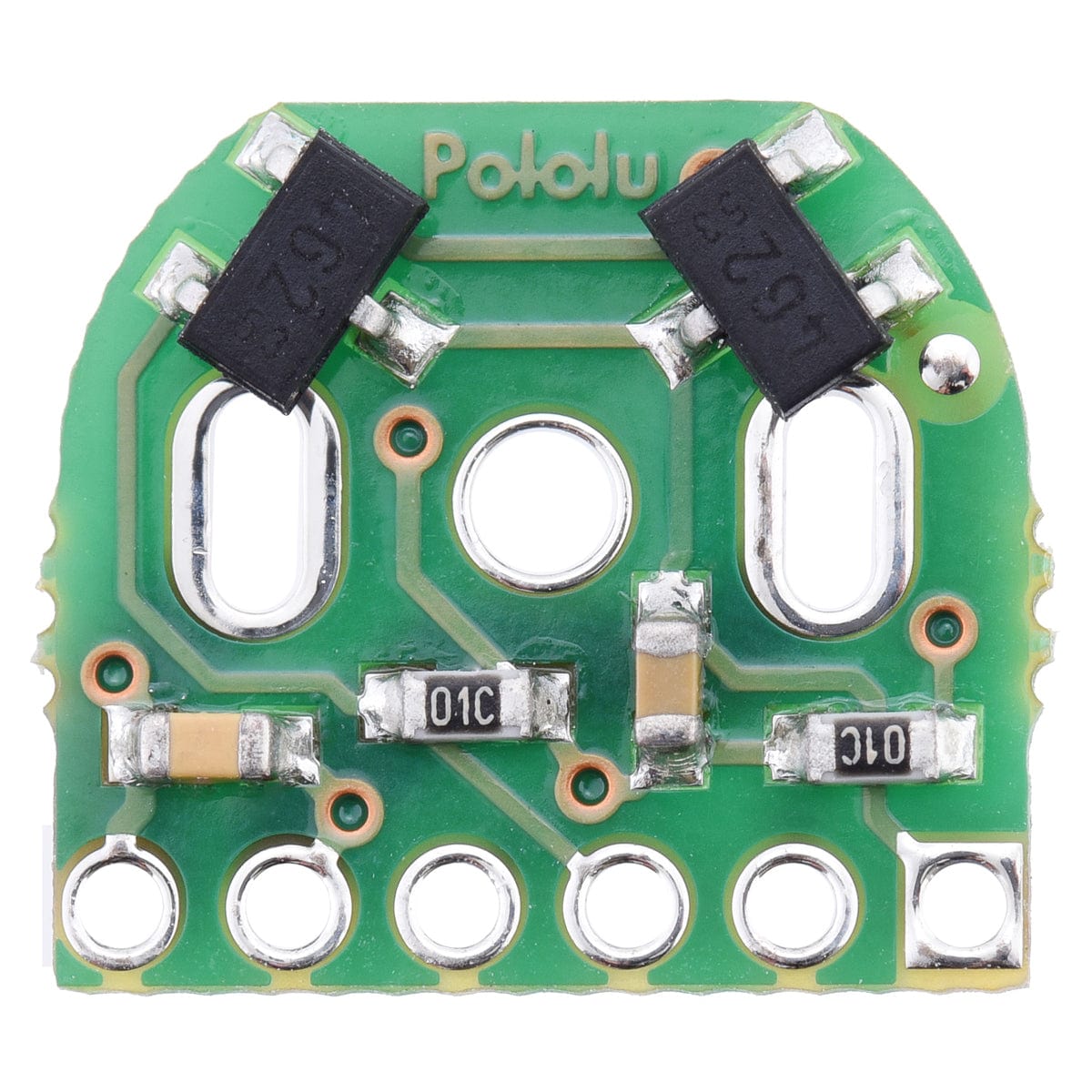
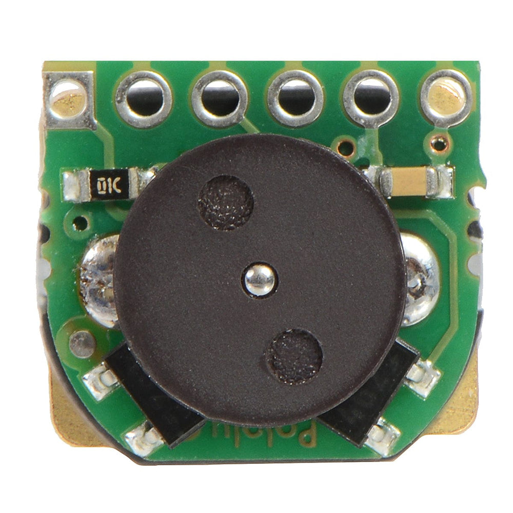
The encoder board is designed to be soldered directly to the back of the motor, with the back shaft of the motor protruding through the hole in the middle of the circuit board. One way to achieve good alignment between the board and the motor is to tack down the board to one motor pin and to solder the other pin only when the board is flat and well aligned. Be careful to avoid prolonged heating of the motor pins, which could deform the plastic end cap of the motor or the motor brushes.
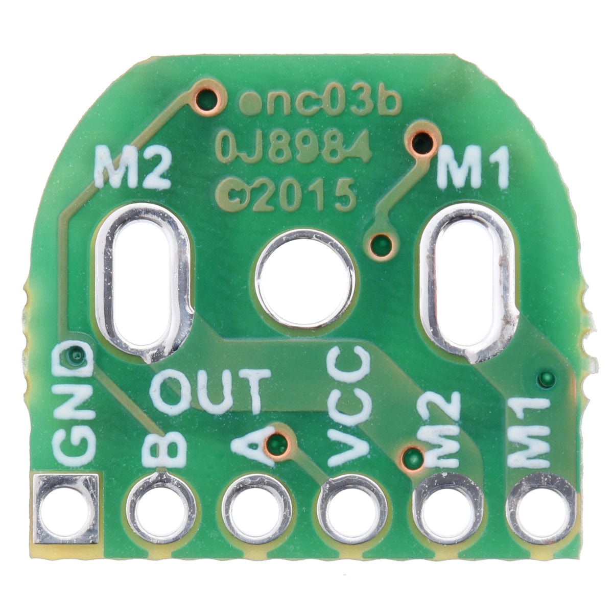
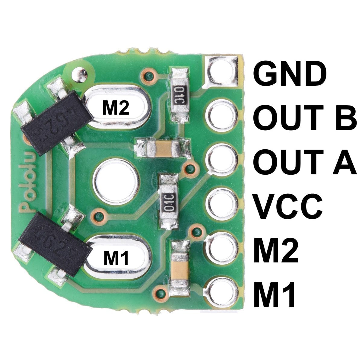
Once the board is soldered down to the two terminals, the motor leads are connected to the M1 and M2 pads along the edge of the board; the remaining four pads are used to power the sensors and access the two quadrature outputs:

The sensors are powered through the VCC and GND pins. VCC can be 2.7 V to 18 V, and the quadrature outputs A and B are digital signals that are either driven low (0 V) by the sensors or pulled to VCC through 10 kΩ pull-up resistors, depending on the applied magnetic field. The sensors’ comparators have built-in hysteresis, which prevents spurious signals in cases where the motor stops near a transition point.
The board’s six pads have a 2 mm pitch, so they do not work with common 0.1″ connectors. One option for connecting to the board is to solder in individual wires, such as in the example below:

Alternatively, you can solder a 2mm-pitch connector to the board. The examples below show a male header, which gives you the option of making a detachable cable terminated by a 6-pin 2mm-pitch female header. If the pins are angled over the motor, as shown in the picture below, they will just barely protrude through the holes in the board. Note that in this orientation, there is room to plug in a female header even when our extended micro metal gearmotor bracket is being used.

If the pins are pointed away from the motor, they will need to be angled so that they sufficiently clear the magnetic disc. With a decent soldering iron, it is possible to solder them in this orientation even after the encoder has been installed on the motor.
Once the board is soldered to the motor, the magnetic encoder disc can be pushed onto the motor shaft. One easy way to accomplish this is to press the motor onto the disc while it is sitting on a flat surface, pushing until the shaft makes contact with that surface. The size of the gap between the encoder disc and the sensor board does not have a big impact on performance as long as the motor shaft is at least all the way through the disc.
| Minimum operating voltage | 2.7V |
| Maximum operating voltage | 18V |
| Connector | none (2mm-pitch through-holes) |
| Size | 10.6 mm × 11.6 mm |
| Weight | 1g |
Motors and pin headers not included
Your payment information is processed securely. We do not store credit card details nor have access to your credit card information.