 Skip to content

Maker Advent Calendar Day #3: Bashing Buttons!
Welcome to day three of your 12 Projects of Codemas Advent Calendar. Today we’ll be adding physical inputs to your program using buttons!
So far we’ve relied purely on code to tell our components and program what to do and when. Now we’re going to use physical buttons to do that, which will act as triggers in our program to determine what happens.
Let's go!
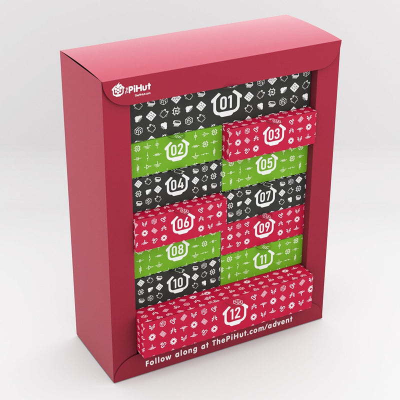
Box #3 Contents
In this box you will find:
- 1x Mini Breadboard
- 3x Tall Tactile Buttons
- 3x Button caps
- 7x Male to male jumper wires

Today’s Project
Today we’ll be programming the buttons in your box as inputs for our code. Whilst we can easily use code to trigger our program to 'do things' (such as counting), components like buttons and switches allow us to physically interact with our project.
Most buttons are very simple, just connecting a circuit together which then sends a signal to our Raspberry Pi Pico via our chosen GPIO pin. You could do the same by simply touching two wires together, but of course buttons make this far more convenient and user friendly.
We're also going to be using the mini breadboard as a little control panel for our project as we’re going to make use of our LED circuit from yesterday. It's a handy part to have in your growing stash of bits, and it'll come in handy for some of our other boxes too.
Oh and the button caps? They're just a nice little extra that make each click that little bit more satisfying! Clickety click click clickety click!
Construct the Circuit
As always, first make sure your Pico is disconnected from your computer.
Now grab the mini breadboard and pop each button into it a few holes apart, making sure the legs sit either side of the little channel in the middle.
Like our larger breadboard, that central channel disconnects one side from the other, which is handy when wiring projects otherwise all of our button legs would be connected together (and we really don't want any magic blue smoke!).

Now we need to connect a 3.3V pin from the Pico to the top red lane on our main breadboard. Pop a jumper wire into the 3V3 (OUT) pin on the Pico (physical pin 36), then connect the other side to the top red lane.
You then need to connect the red 3.3V lane to one side of each of the buttons, go for the right side like we have below:

Lastly we need to connect the other side of the buttons to GPIO pins. Add a jumper wire into GPIO 13, 8 and 3 (that's physical pins 17, 11 and 5). Check the Pico pin map if you're not sure, or use our diagram below.

Important: the GPIO pin must be on the opposite side of the button, as the left and right side are disconnected until you click the button. If you had the GPIO and 3.3V wires on one side, the button would act as if it's constantly clicked!
Activity 1: Button Test Program
We'll first run a simple test program on one of the buttons. Each button has been wired to a GPIO pin (13, 8 and 3) so we can set these as inputs to trigger some text to print when they're pressed.
We'll use a while loop (which we learnt about yesterday) so that the program keeps watching for the button press forever, with a new function, an if statement, to determine what happens when the button is pressed.
If Statements
If you've used Microsoft Excel or similar software previously, you'll have already guessed what if statements do.
If statements allow us to give our code different outcomes depending on values, inputs and many other things, such as "if the first button is pressed, light the red LED" . If the condition for the statement is met, our program will run the code inside that code block which is indented underneath.
Indentation is important again here - the while loop block is indented, but as the while loop contains an if statement, we indent yet again for the if statement block of code. Look at the example below to see this in action.
If statements can be very powerful and there are lots of different and advanced ways to use them. You'll use them lots when making your own code. We'll start with a nice simple example, but first let's explain something else new in our code - pull downs.
Pull downs
Our code below also uses pull downs - you can see this at the end of each of the button set up sections as Pin.PULL_DOWN.
So why do we add this? When we use a button, we're sending 3.3V to the GPIO pin to set it HIGH, however we need to make sure the pin is LOW in the first place or our code might not be able to detect the change and/or it might trigger itself randomly.
This is because GPIO pins with no pull down (or pull up) can be 'floating' between 0V and 3.3V - 'pulling down' the pin to 0V ensures it's always LOW to start with.
Sometimes this is achieved by using physical resistors in a circuit, however some microcontrollers (such as our Pico) have this functionality built-in and we can simply enable them in our code. Handy!
The Code
This initial simple code uses just the first button. The code includes our usual imports and pin setup, then starts a while loop. The while loop contains an if statement that looks for a HIGH signal (1) on GPIO 13.
If the button is pressed and a signal is sent to that pin, our code will print "button 1 pressed".
We include a short delay in this loop to give your finger a chance to release the button, to avoid the code triggering many times from a single press (known as 'debouncing'). Values of 0.1 or 0.2 seconds usually work well.
Copy the example over to Thonny and give it a go:
# Imports
from machine import Pin
import time

# Set up our button name and GPIO pin number
# Also set the pin as an input and use a pull down
button1 = Pin(13, Pin.IN, Pin.PULL_DOWN)

while True: # Loop forever

    time.sleep(0.2) # Short delay

    if button1.value() == 1: #If button 1 is pressed
        print("Button 1 pressed")
Activity 2: Multiple Button Inputs
Let's add our other buttons into the code and change our if statement to make it watch for any of them being pressed.
To do this, we add setup lines for the other buttons, then add additional if statements below the original one - our code will simply check each condition, in order.
If one of the conditions is met (if a button is pressed) it will run the code for that button and then continue to check the remaining statements (and it will do this forever, because we have this in a while True loop):
# Imports
from machine import Pin
import time

# Set up our button names and GPIO pin numbers
# Also set pins as inputs and use pull downs
button1 = Pin(13, Pin.IN, Pin.PULL_DOWN)
button2 = Pin(8, Pin.IN, Pin.PULL_DOWN)
button3 = Pin(3, Pin.IN, Pin.PULL_DOWN)

while True: # Loop forever

    time.sleep(0.2) # Short Delay

    if button1.value() == 1: # If button 1 is pressed

        print("Button 1 pressed")

    if button2.value() == 1: # If button 2 is pressed

        print("Button 2 pressed")

    if button3.value() == 1: # If button 3 is pressed

        print("Button 3 pressed")
Activity 3: Multiple Button Inputs with elif and else
What if we wanted to do something more advanced with our buttons?
Maybe we want to ignore buttons 2 and 3 if button 1 is pressed? Do we want something else to happen if none of the buttons are pressed? Perhaps we want something to happen if we hold two buttons down at the same time?
We can do many of these things, and more, by using our if statement with additional statements elif and else. Let's explain how they work before we try them:
The elif statement
The elif statement is short for 'else if'. If your first if statement isn't true, your code will then check each elif statement in order to see if any of those are true.
If one of the elif statements triggers, it will run the code block for that statement only and then stop checking the others in the loop (unlike regular if statements which keep checking each one after the other regardless of what happens).
In the example below, we use if then elif to tell our code to check if button 1 is being pressed, and if not, check button 2, and if button 2 isn't being pressed, check button 3.
Tip: There should always be an initial 'if' statement first
# Imports
from machine import Pin
import time

# Set up our button names and GPIO pin numbers
# Also set pins as inputs and use pull downs
button1 = Pin(13, Pin.IN, Pin.PULL_DOWN)
button2 = Pin(8, Pin.IN, Pin.PULL_DOWN)
button3 = Pin(3, Pin.IN, Pin.PULL_DOWN)

while True: # Loop forever

    time.sleep(0.2) # Short Delay

    if button1.value() == 1: # If button 1 is pressed

        print("Button 1 pressed")

    elif button2.value() == 1: # If button 2 is pressed

        print("Button 2 pressed")

    elif button3.value() == 1: # If button 3 is pressed

        print("Button 3 pressed")
The else statement
The else statement says "if none of the statements above have their conditions met, do this instead". It can be useful if you want something to always happen when none of the above if/elif statements are being met.
Here's a short example (using just two buttons) you can try where we always print "No button presses" if none of the buttons are being pressed. The commentary shows you where the else statement is being used:
# Imports
from machine import Pin
import time

# Set up our button names and GPIO pin numbers
# Also set pins as inputs and use pull downs
button1 = Pin(13, Pin.IN, Pin.PULL_DOWN)
button2 = Pin(8, Pin.IN, Pin.PULL_DOWN)

while True: # Loop forever

    time.sleep(0.2) # Short Delay

    if button1.value() == 1: # If button 1 is pressed

        print("Button 1 pressed")

    elif button2.value() == 1: # If button 2 is pressed

        print("Button 2 pressed")

    else: # If no buttons are being pressed

        print("No button presses")
The Code
Now that we know what elif and else do, let's put them to work whilst adding our LEDs back into our program.
The code below first checks if we've held buttons 1 and 2 together. It does this by using an if statement with 'and' between two conditions, asking for both of these to be met at the same time. If the buttons are both held down, the green LED will light.
We then use an elif statement to check if button 1 is being pressed on its own, if so, the amber LED will light.
Then we use an else statement to light the red LED (and turn all others off) if nothing is being pressed. Button 3 isn't being used for this example. All of this is in a while True loop to make it run forever:
# Imports
from machine import Pin
import time

# Set up our button names and GPIO pin numbers
# Also set pins as inputs and use pull downs
button1 = Pin(13, Pin.IN, Pin.PULL_DOWN)
button2 = Pin(8, Pin.IN, Pin.PULL_DOWN)
button3 = Pin(3, Pin.IN, Pin.PULL_DOWN)

# Set up our LED names and GPIO pin numbers
red = Pin(18, Pin.OUT)
amber = Pin(19, Pin.OUT)
green = Pin(20, Pin.OUT)

while True: # Loop forever

    time.sleep(0.2) # Short Delay

    if button1.value() == 1 and button2.value() == 1: # If button 1 and 2 are pressed at the same

        print("Buttons 1 and 2 pressed")
        green.value(1) # green LED on
        red.value(0) # red LED off

    elif button1.value() == 1: # If button 1 is pressed

        print("Button 1 pressed")
        amber.value(1) # amber LED on
        red.value(0) # red LED off

    else: # If no buttons are being pressed

        red.value(1) # red LED on
        amber.value(0) # amber LED off
        green.value(0) # green LED off
Activity 4: This button or that button?
Another trick we can use with buttons and if statements is to use 'or' between conditions to check if one of our buttons is being pressed - but make them all trigger the same result.
We've added an example below which looks for either button 1 or 2 being pressed.
Once you've tried it, why not have a go at adding button 3 back into the code, and then make all three buttons trigger the LED (hint: just add another 'or' to the same line in the same way):
# Imports
from machine import Pin
import time

# Set up our button names and GPIO pin numbers
# Also set pins as inputs and use pull downs
button1 = Pin(13, Pin.IN, Pin.PULL_DOWN)
button2 = Pin(8, Pin.IN, Pin.PULL_DOWN)

# Set up our LED names and GPIO pin numbers
green = Pin(20, Pin.OUT)

while True: # Loop forever

    time.sleep(0.2) # Short Delay

    if button1.value() == 1 or button2.value() == 1: # If button 1 OR button 2 is pressed

        print("Button 1 or 2 pressed")

        green.value(1) # green LED on
        time.sleep(2)
        green.value(0) # green LED off
Activity 5: Toggling with buttons
Another handy feature we can use with GPIO pins is 'toggle'. As you might have guessed, this toggles a pin's status from HIGH to LOW to HIGH and so on.
The example below is mostly the same but uses button 1 to toggle the red LED on and off.
Once you've tried the code below, why not try adding the other buttons and LEDs back in, toggling each of them?
# Imports
from machine import Pin
import time

# Set up our button names and GPIO pin numbers
# Also set pins as inputs and use pull downs
button1 = Pin(13, Pin.IN, Pin.PULL_DOWN)

# Set up our LED names and GPIO pin numbers
red = Pin(18, Pin.OUT)

while True: # Loop forever

    time.sleep(0.5) # Short delay

    if button1.value() == 1: #If button 1 is pressed

        print("Button 1 pressed")

        red.toggle() # Toggle Red LED on/off
Day #3 Complete!
Great job makers, you’ve now got the skills to use physical inputs with MicroPython (which will come in handy for the rest of the calendar) and can code if statements in all sorts of interesting new ways!
Today you have learnt:
- How to create a circuit with physical inputs
- How to code physical inputs with MicroPython
- What if statements are and how to use them
- How to use elif and else within if statements
- How to use 'and and 'or' within if statement conditions
- Combined physical inputs with physical outputs
As always, please do not disassemble the circuit until tomorrow where we will explore the next fun component - see you then!
We used Fritzing to create the breadboard wiring diagram images for this page.


44 comments
Chris Wolsey
@ZSleyer traffic light code formatted correctly in paste bin
https://pastebin.com/TJABCvrV
@ZSleyer traffic light code formatted correctly in paste bin
https://pastebin.com/TJABCvrV
The Pi Hut
@Theo – if you don’t pull the pin UP or DOWN, there’s no signal pushing the pin one way or another, so it’ll be ‘floating’. While floating, any local interference can make the state of the pin randomly trigger HIGH or LOW. This is why we ‘pull the pin down’ to a definite, solid 0V. This way we can rely on the pin to only show as HIGH (when we press the button) when we push a definite 3.3V through it, as any minor interference won’t be enough to trigger that HIGH state.
@Theo – if you don’t pull the pin UP or DOWN, there’s no signal pushing the pin one way or another, so it’ll be ‘floating’. While floating, any local interference can make the state of the pin randomly trigger HIGH or LOW. This is why we ‘pull the pin down’ to a definite, solid 0V. This way we can rely on the pin to only show as HIGH (when we press the button) when we push a definite 3.3V through it, as any minor interference won’t be enough to trigger that HIGH state.
Theo
While trying to get my head around Pull.Down, I ran this piece of code.
from machine import Pin
import time
button1 = Pin(13, Pin.IN)
while True:
time.sleep(0.2)
print(button1.value())
If you leave it running, and don’t touch anything, the value will occasionally and randomly change from 0 to 1 or 1 to 0. Why might this be?
Luke
Whack-a-mole game i made!
https://pastebin.com/NuiPVZtc
Whack-a-mole game i made!
https://pastebin.com/NuiPVZtc
Mat
In case anyone else makes the same error as me: make sure your code checks the value is actually 1! For some reason I wrote button2.value() == 2 and button3.value() == 3, and I thought I had got something wrong with the circuit.
In case anyone else makes the same error as me: make sure your code checks the value is actually 1! For some reason I wrote button2.value() == 2 and button3.value() == 3, and I thought I had got something wrong with the circuit.
ZSleyer
I’ve made a simple traffic Light controlled with the 3 Buttons
Importsfrom machine import Pin
import time Set up our button names and GPIO pin numbers Also set pins as inputs and use pull downs
button1 = Pin(13, Pin.IN, Pin.PULL_DOWN)
button2 = Pin(8, Pin.IN, Pin.PULL_DOWN)
button3 = Pin(3, Pin.IN, Pin.PULL_DOWN) Set up our LED names and GPIO pin numbers
red = Pin(18, Pin.OUT)
amber = Pin(19, Pin.OUT)
green = Pin(20, Pin.OUT) seconds
light_delay = 1
def traffic_light(r, a, g):
red.value®
amber.value(a)
green.value(g)
time.sleep(light_delay)
def traffic_light_from_green_to_red():
traffic_light(0, 0, 1)
traffic_light(0, 1, 0)
traffic_light(1, 0, 0)
def traffic_light_from_red_to_green():
traffic_light(1, 0, 0)
traffic_light(1, 1, 0)
traffic_light(0, 0, 1)
def traffic_light_off():
for i in range (1,20):
traffic_light(0,1,0)
traffic_light(0,0,0)
if button1.value() == 1:
print(“break”)
break
if button2.value() == 1:
print(“break”)
break
traffic_light(0, 0, 0)
print(“Button 1 pressed”) traffic_light_from_red_to_green() if button2.value() == 1: #If button 1 is pressed print(“Button 2 pressed”) traffic_light_from_green_to_red() if button3.value() == 1: print(“Button 3 pressed”) traffic_light_off()while True: # Loop forever
if button1.value() == 1: #If button 1 is pressed
greetings from Germany :)
Martin
@Albie Mechanical Mechanical switches like these bounce when they switch, so if your code is running very quickly it will see multiple on offs before the switch settles. You would usually debounce a switch like this but for simplicity that hasn’t been done. A very simple way is to read the pin, wait a little, read it again and do that a couple of times and that act on it. If memory serves correct (from about 17 years ago) a total debouce time of about 200 us will keep it responsive enough, but not too responsive.
@Albie Mechanical Mechanical switches like these bounce when they switch, so if your code is running very quickly it will see multiple on offs before the switch settles. You would usually debounce a switch like this but for simplicity that hasn’t been done. A very simple way is to read the pin, wait a little, read it again and do that a couple of times and that act on it. If memory serves correct (from about 17 years ago) a total debouce time of about 200 us will keep it responsive enough, but not too responsive.
The Pi Hut
@Ethan Marsden – A slight rotation/twist can help them ‘find their way’. Sometimes they just get caught on something in the breadboard and rotating them slightly helps that.
@Ethan Marsden – A slight rotation/twist can help them ‘find their way’. Sometimes they just get caught on something in the breadboard and rotating them slightly helps that.
Ethan Marsden
Hello, I was wondering if there is an easier way to insert components into the solderless breadboard? Some of my male jumper wires have broken when I ws inserting them.
Hello, I was wondering if there is an easier way to insert components into the solderless breadboard? Some of my male jumper wires have broken when I ws inserting them.
anonymous
Loving it so far!
Loving it so far!
The Pi Hut
@Albie – The toggle in activity #5 should just change the LED from one state to another (ON or OFF). You may want to double-check your circuit for any errors, or if that’s fine, increase the delay slightly to avoid the button registering two presses.
@Albie – The toggle in activity #5 should just change the LED from one state to another (ON or OFF). You may want to double-check your circuit for any errors, or if that’s fine, increase the delay slightly to avoid the button registering two presses.
Albie
Loving it so far, but on Activity 5, is there any way to make it so that it doesn’t make me press the button ~10 times, before the light stays permanently on?
Loving it so far, but on Activity 5, is there any way to make it so that it doesn’t make me press the button ~10 times, before the light stays permanently on?
Scott
Are there buttons that use the 5v side of things?
Are there buttons that use the 5v side of things?
The Pi Hut
@UnfinishedStuff You know what, you’re right! That would make more sense. Thanks, we’ll update the code.
@UnfinishedStuff You know what, you’re right! That would make more sense. Thanks, we’ll update the code.
Jaap
Very nice practical builds and examples, Santa can’t be wrong with this and helps understanding how digital systems and electronics work. Love the examples of other customers provided in the comments, thanks for that too!
Very nice practical builds and examples, Santa can’t be wrong with this and helps understanding how digital systems and electronics work. Love the examples of other customers provided in the comments, thanks for that too!
UnfinishedStuff
I’m just working through this and having fun converting it to C/++ code. In the final aprt of Activity 3, should the if and elif sections not have lines turning off the red LED? Otherwise it seems to turn on the first time no buttons are pressed, and then it never goes out.
I’m just working through this and having fun converting it to C/++ code. In the final aprt of Activity 3, should the if and elif sections not have lines turning off the red LED? Otherwise it seems to turn on the first time no buttons are pressed, and then it never goes out.
The Pi Hut
@Jude We cover this at a high level here but we’re trying to balance the fine line between giving just enough info to know what’s going on, and overwhelming with the nitty-gritty of how things work.
We wanted the calendar to be a non-scary, gentle introduction to coding and electronics, which we hope lays the foundations to make people want to go off into the wild after day 12 and start finding new ways to use Python, new components, new project examples and crucially, more detailed information on electronics and how things work.
It can be a tricky thing to balance so we approached this from our own experiences. For example, personally I (Rich, Product Manager) hate it when teachers jump straight into not-so-plain-English using words like “parenthesis” instead of “brackets” or “string” instead of “text” – yes these are the ‘right’ terms, but that doesn’t matter too much on your first week into coding and can cause more confusion. I think it’s much more important to not scare anyone off, then gradually start using these terms more as the days go on.
Similarly with the electronics side of things, we don’t want to get too bogged down in the ‘how’ just yet…we want to make it fun and as snappy as possible, because it’s much more important to us that you simply stick with it because by day 12 you’ll then be “ONE OF US” finding your own answers with your new-found confidence :D
Jude
Is there a day dedicated to understanding more about the breadboard and the chip? For example why does a button connected to “+” and pin 5 control an LED?
Is there a day dedicated to understanding more about the breadboard and the chip? For example why does a button connected to “+” and pin 5 control an LED?
The Pi Hut
@Jakub You may find that one of the button’s legs has bent the wrong way or may not be seated in the breadboard correctly. It’s also worth removing all wires and fitting them again, just to make sure they’re all connecting properly and in the right holes on the breadboard/pico.
@Jakub You may find that one of the button’s legs has bent the wrong way or may not be seated in the breadboard correctly. It’s also worth removing all wires and fitting them again, just to make sure they’re all connecting properly and in the right holes on the breadboard/pico.
Jakub
i have a problem where the middle button doesn’t work
i have a problem where the middle button doesn’t work
Sandy
@James might be worth double checking the wire from the button is plugged into the breadboard slot with the number 17 next to it as opposed to 13. Only because the code calls on pin 13 (but it means GPIO pin 13) which is actually the physical pin 17 and physical pin 13 is GND, which would cause your short. Just an idea on what might be causing it; hope you get your issue sorted soon :)
@James might be worth double checking the wire from the button is plugged into the breadboard slot with the number 17 next to it as opposed to 13. Only because the code calls on pin 13 (but it means GPIO pin 13) which is actually the physical pin 17 and physical pin 13 is GND, which would cause your short. Just an idea on what might be causing it; hope you get your issue sorted soon :)
The Pi Hut
@James – Sounds like you’re shorting the Picos GND and 3.3V lines, remove everything and start from scratch, and if you’re still stuck pop us a photo of your circuit to support.thepihut.com and we’ll take a look for you.
@James – Sounds like you’re shorting the Picos GND and 3.3V lines, remove everything and start from scratch, and if you’re still stuck pop us a photo of your circuit to support.thepihut.com and we’ll take a look for you.
The Pi Hut
@Josh Make sure your Pico is fully inserted into the breadboard. No metal legs should be visible when fully inserted, and the black plastic parts on the Pico should be flush with the top of the breadboard.
@Josh Make sure your Pico is fully inserted into the breadboard. No metal legs should be visible when fully inserted, and the black plastic parts on the Pico should be flush with the top of the breadboard.
Josh
I am a few days behind the calendar. So far it has been great with one small issue.
To make these examples work I need to press down on either end of the Pi to ensure the pins make good contact with the board. It gets hard to do projects where pressing other things, like buttons, is required.
Does anyone have any advice?
Harold
Great!!
I too have been planning to play with the Raspberry Pico and learn MicroPython ever since it came out. Now this wonderful advent calendar is giving me the motivation to actually do so.
Thank you
Great!!
I too have been planning to play with the Raspberry Pico and learn MicroPython ever since it came out. Now this wonderful advent calendar is giving me the motivation to actually do so.
Thank you
The Pi Hut
@Stephen Roberts If you pop back to day #2 this is explained briefly – the physical pins numbers are the logical (in order) numbers of the physical pins from 1 to 40 on the Pico itself. We then have the somewhat scattered GPIO pin numbers which we use in our code. Some makers prefer working with physical pin numbers, while others prefer GPIO numbers, so we always add both.
Breadboards are generic and can be used with any breadboard-compatible development board. So the numbering is purely the breadboard’s lane numbering and isn’t related to the Pico at all. We do try to make some use of these where we can, hence why we’ve plugged our breadboard into the end starting with 1. That works for one side of course (pins 1-20), but the other side (pins 21-40) won’t match the Pico. Hope that helps.
stephen Roberts
Our calendar arrived late so im behond on each day lol
hoping you can explain. Why do you refer to the pins as physical pins with different numbers. on the pico the number seem to match the breadboard. Just a little confused about what you meant
Our calendar arrived late so im behond on each day lol
hoping you can explain. Why do you refer to the pins as physical pins with different numbers. on the pico the number seem to match the breadboard. Just a little confused about what you meant
Matt
I have to say I am a little behind due to work and only just finished day 3 but these are ace :-)
I have to say I am a little behind due to work and only just finished day 3 but these are ace :-)
James
Hi, I’ve built this, checked everything and rebuilt it, even tried a different computer. But every time I press one of the buttons it restarts the Pico and disconnects it from my machine.
Hi, I’ve built this, checked everything and rebuilt it, even tried a different computer. But every time I press one of the buttons it restarts the Pico and disconnects it from my machine.
Fran
Since day 3 has added buttons with the LED’s so only one thing that can be made, a Simon game. Have kept the design in the same style as the PiHut and not used Functions, however it is a simple script that can be expanded upon.
https://github.com/frantek/PiHut-Advent/blob/master/Day%203/Day_3_simon.py
The Pi Hut
@Michael – Breadboards can be a little fiddly like that, sometimes the internal metal parts move around a little. We find they usually sort themselves out after they’ve had jumper wires pushed in some of the holes next to them, but if not, just drop us a quick message via support.thepihut.com and we’ll get a replacement out to you.
@Michael – Breadboards can be a little fiddly like that, sometimes the internal metal parts move around a little. We find they usually sort themselves out after they’ve had jumper wires pushed in some of the holes next to them, but if not, just drop us a quick message via support.thepihut.com and we’ll get a replacement out to you.
Jonny
Please ignore my previous comment, unless you want to let everyone know the fix seems to have been that in device management for my USB hub, there was the checkbox to turn off the hub to save power. Unticking that seems to have fixed it for now :)
Please ignore my previous comment, unless you want to let everyone know the fix seems to have been that in device management for my USB hub, there was the checkbox to turn off the hub to save power. Unticking that seems to have fixed it for now :)
Jonny
Is there any chance my PC USB port is not putting out enough voltage to power everything?
I seem to either be able to get button 1 working and the three LEDs, or all three buttons but only 1 LED? Very odd! Was convinced a part was broken but I’ve swapped them out one by one to see if they’re working and they all are.
Michael
Hi,
I’ve been a bit late getting to this day but I’m having trouble with the mini breadboard, where button 2 is its not doing anything, i’ve changed the wires around, the buttons but offsetting it slightly by a set of holes seems to sort it out, is this going to cause problems later on?
Hi,
I’ve been a bit late getting to this day but I’m having trouble with the mini breadboard, where button 2 is its not doing anything, i’ve changed the wires around, the buttons but offsetting it slightly by a set of holes seems to sort it out, is this going to cause problems later on?
Colin
This is great fun…
Three days in, and they may be simple projects, but this has been an absolute blast (and even if I am running a day behind. That’s ok – it will eek the Advent joy even further…) Already dreaming of what else Santa might bring… Big Buttons… Speakers and Screens etc…
Hadn’t played with my other Raspberry Pi stuff recently but this has reinvigorated that just in time for the holidays…
Without wishing away this year and what we still have to come… This is much better than a box of chocolates… and I hope there will be a new version for 2023 with different projects :-)
The Pi Hut
@Al No problem, that’s working as expected. Activity 1 is just to show the button working by printing that line to Thonny. The LEDs are still wired up on your circuit, but we don’t use any code in the first two examples to control them (just to keep things as clear as possible whilst we show you how the buttons work).
We introduce the LEDs back into the code from Activity 3 once we’ve got the hang of the buttons. Hope that helps.
Al
Is a light supposed to light up when a button is pressed in Activity 1: Button Test Program?
my lights work as per the codes given on day 2. I’ve checked all the wires and it looks like the picture but no light is coming on. It prints the text ‘Button 1 pressed’ in the shell window.
This is the first time I’ve tried this so I don’t know what to do when it doesn’t work.
The Pi Hut
@Gavin The wire colours in each kit may vary as this is how they come from the factory (similar to many of our jumper wire packs in mixed colours). It’s a fantastic suggestion for next year’s calendar though, as you say it would simply help even more with wiring clarity. I think after years of using rainbow colour jumper wires we simply didn’t spot this obvious improvement. Thanks.
@Gavin The wire colours in each kit may vary as this is how they come from the factory (similar to many of our jumper wire packs in mixed colours). It’s a fantastic suggestion for next year’s calendar though, as you say it would simply help even more with wiring clarity. I think after years of using rainbow colour jumper wires we simply didn’t spot this obvious improvement. Thanks.
The Pi Hut
@Jerry311 I see what you mean – unfortunately this is the default syntax highlighting style that our website is currently running (which is better than the old all-grey it used to be, but perhaps could be better). We’ll ask our web developers if they have any other style options we can use. Thanks for the suggestion!
@Jerry311 I see what you mean – unfortunately this is the default syntax highlighting style that our website is currently running (which is better than the old all-grey it used to be, but perhaps could be better). We’ll ask our web developers if they have any other style options we can use. Thanks for the suggestion!
The Pi Hut
@Julie Oh no :( sorry about that, it must have been a packing error at the factory. Please drop Billie a quick message via support.thepihut.com and she’ll get a new pack sent out to you. Don’t worry – it won’t stop you from continuing with most of the upcoming boxes and activities.
@Julie Oh no :( sorry about that, it must have been a packing error at the factory. Please drop Billie a quick message via support.thepihut.com and she’ll get a new pack sent out to you. Don’t worry – it won’t stop you from continuing with most of the upcoming boxes and activities.
M.K
nice
nice
Julie Hunt
Disaster! There are no buttons in my box! I have only got the breadboard and jumper wires. I’ve checked all the boxes and they are not in anywhere. What should I do now?
Disaster! There are no buttons in my box! I have only got the breadboard and jumper wires. I’ve checked all the boxes and they are not in anywhere. What should I do now?
jerry311
I find it misleading (at least for me) that all the colons are in the same grey color as the comments.
Would it be possible change the colors in t code formatting a bit?
Maybe use the same blue as the ‘while’ or ‘if’ they belong together anyway.
I find it misleading (at least for me) that all the colons are in the same grey color as the comments.
Would it be possible change the colors in t code formatting a bit?
Maybe use the same blue as the ‘while’ or ‘if’ they belong together anyway.
Gavin
While I’m enjoying this, as learning python basics has been on my to do list forever, and I dont know if it was changed in later kits, but my “1st edition” i.e. the inital batch came with white jumper wires. Coloured wires that would match the images may have made it a little easier to see you had the right wire in the right holes.
While I’m enjoying this, as learning python basics has been on my to do list forever, and I dont know if it was changed in later kits, but my “1st edition” i.e. the inital batch came with white jumper wires. Coloured wires that would match the images may have made it a little easier to see you had the right wire in the right holes.