 Skip to content

Let it Glow Maker Advent Calendar Day #4: Brilliant Bar Graphs!
It’s day #4 of the Let it Glow Maker Advent Calendar!
Today you'll find a new blinky component - one of our favourites in fact - a bar graph display. Whilst essentially it's just a set of five LEDs in a row, the compact size and closeness of the LEDs means you can make some really cool effects and projects with these. They're great for displaying progress, counts and other data.
We're going to re-use a lot of our knowledge from the last few boxes and add a few new tricks to make some fun little projects.
Let’s get to it!
Box #4 Contents
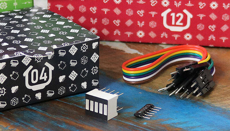
In this box you will find:
- 1x 5-segment bar graph display
- 1x Network resistor
- 6x Male to male jumper wires
Today’s Activities
Today we’re going to learn how to use a bar graph display, including wiring it up with the network resistor in your box (we'll explain what these handy little resistors are in a moment).
We'll use the LEDs to display information from our code, and also show you how to make some nice effects with these.
First, let's tell you a little more about today's components...
How does a bar graph display work?
We already know what an LED is and how they have two legs, one the anode (+) and the other the cathode (-).
A bar graph display works in exactly the same way - it just has more than one LED, which means it has more legs!
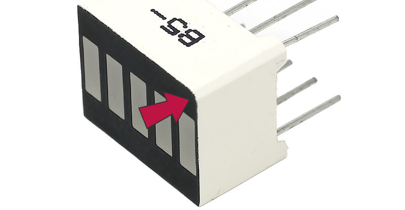
You'll notice the legs are all the same length too, so how do we know which leg is which? If you look closely, you'll see that one of the corners of the display has a flat edge - this indicates that the pins on that side are the GND/cathode(-) pins. Many components use this kind of approach to indicate polarity.
We just hook up each LED's leg to a GPIO pin and the other to GND (via a resistor) and we're ready to code!
How does a network resistor work?
When you're dealing with multiple LEDs, like we are with our bar graph display, it can get very fiddly trying to carefully fit lots of those skinny traditional resistors into a breadboard right next to eachother.
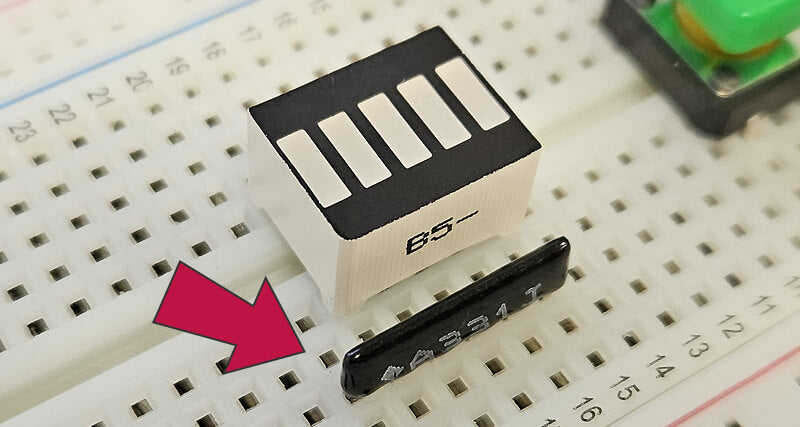
In this scenario, we prefer to use network resistors (also known as resistor arrays, resistor packages or resistor networks). This little black component essentially has five resistors inside, and a single pin to hook them all up to GND, taking away lots of work for us messing around with individual resistors and wires.
Notice how the body of the network resistor has a dot next to the letter A? That dot is the common GND pin. Let's get our circuit wired up and we'll show you exactly where everything goes.
Construct the Circuit
As always, make sure your Pico is disconnected from the USB cable when working on the circuit.
Prepare the breadboard
First, remove the LED, resistor and their wires from the circuit and put them back into box #2. We won't use that for today's activities. Leave the two buttons in place for now.
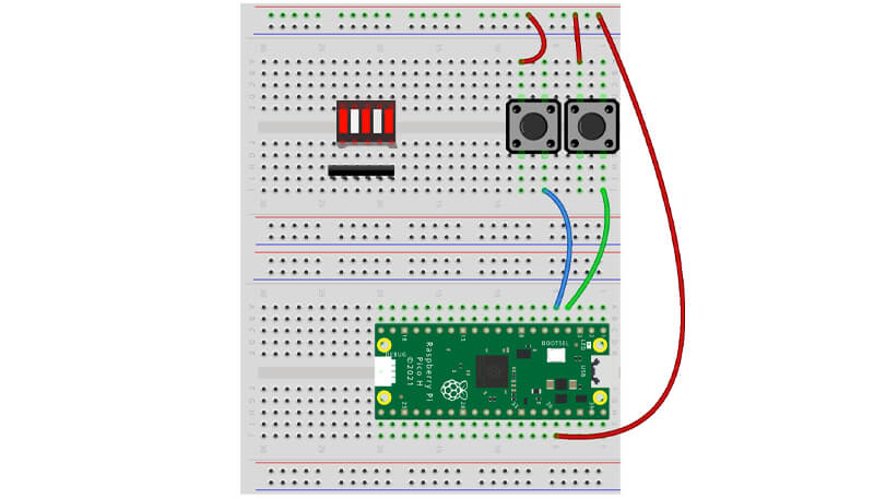
Your starting point should look like this:

Fit the bar graph & network resistor
Grab your bar graph display and fit that to the breadboard, straddling the central break, with the GND pins/flat corner edge to the lower side:
Now fit the network resistor. Locate the dot marked next to the 'A' - the first pin here isn't connected to our bar graph display as it's the GND pin.
Fit the resistor so that all the other pins attach to a leg on our bar graph display, like this (also notice the flat edge and text on the display):
Your breadboard should now look similar to this:
Fit the jumper wires
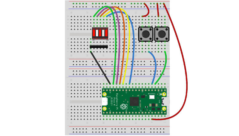
Now to wire it up. Start with the GND wire - connect one end to the GND pin at physical pin 18 and then connect the other end to the 'dot' pin on the network resistor.
Now for the GPIO pins. Each of the LED segments (all five of them) need their own GPIO pin so that we can control them individually.
To start with, we've used GPIO 13, 12, 11 and 10 as they're in a convenient row on the Pico (physical pins 17, 16, 15, 14). We've then connected the final 5th LED segment to GPIO 9 (physical pin 12). Careful - there's a GND pin between GPIO 10 and 9.
Here's what it looks like:
A few tips & pointers
- We're using more wires here, which means more chances to get something wrong! Double-check your circuit before plugging your Pico in.
- The main things to check
- The flat edge on the display is the same side as the network resistor
- The network resistor 'dot pin' is not connected to the display (should only connect to our GND wire)
- You have the Pico-end of the wiring correct, including a gap between the first four GPIO pins and the last one.
All good? Plug your Pico's USB cable back in and let's continue!
Activity 1: Segment test
We'll start with some simple test code to confirm our circuit is wired up correctly and working as expected.
The test code below uses everything we've learnt before and nothing new - so you should be able to understand what it's doing.
Remember that we said that the display is essentially just five LEDs? That's how we're coding it, setting up the five GPIO pins as LEDs just like on day #2.
The script below should light up the segments one-by-one, then turn them all off - if it doesn't, go back and check your wiring (sometimes it helps to just start again if you're unsure).
from machine import Pin
import time

# Set up the LED pins
seg1 = Pin(13, Pin.OUT)
seg2 = Pin(12, Pin.OUT)
seg3 = Pin(11, Pin.OUT)
seg4 = Pin(10, Pin.OUT)
seg5 = Pin(9, Pin.OUT)

# Turn on each LED at a time
seg1.value(1)
time.sleep(1)

seg2.value(1)
time.sleep(1)

seg3.value(1)
time.sleep(1)

seg4.value(1)
time.sleep(1)

seg5.value(1)
time.sleep(1)

# Turn all LEDs off
seg1.value(0)
seg2.value(0)
seg3.value(0)
seg4.value(0)
seg5.value(0)
Activity 2: Easier segment control with lists
Did you notice how long that code was just to turn the LEDs on and then off again? This is because we're now dealing with five different LEDs and GPIO pins to control them - lots of lines!
There are better ways to manage lots of things like this, such as using a list in a for loop.
We covered for loops on day #2 with the range function, but this time we'll use for loops with a list.
What is a list in MicroPython?
In MicroPython, a list is a place to store a number of things (such as our LEDs) that we can refer to in our code by using the name of the list.
Let's jump straight into it with an example.
The code below sets up our LED pins but then adds them all to a list called 'segments'. We then refer to this list in our for loop, which will turn on each LED in our list with a second delay after.
The program keeps running through the list in this for loop until it reaches the last item, then will carry on with any code below it.
Finally we run another for loop to turn all LEDs off (without any delay).
Remember: you don't have to use 'for led'. It can be 'for i' or 'for x' or something else. It doesn't matter either way - you could even use 'for santa' if you wanted!
Just make sure you use the same in your indented code i.e. 'santa.value(1)'
Here's the example code:
from machine import Pin
import time

# Set up the LED pins
seg1 = Pin(13, Pin.OUT)
seg2 = Pin(12, Pin.OUT)
seg3 = Pin(11, Pin.OUT)
seg4 = Pin(10, Pin.OUT)
seg5 = Pin(9, Pin.OUT)

# Create a list of our LEDs
segments = [seg1, seg2, seg3, seg4, seg5]

# For loop to turn each LED on one-by-one
for led in segments:

    led.value(1)
    time.sleep(1)

# For loop to turn off all LEDs

for led in segments:

    led.value(0)
Activity 3: LED scanner
Time to have a bit of blinky fun! We're going to create an LED scanner that runs from one side to the other. A famous example of this is the car from Knight Rider, a classic 80's TV show where the vehicle had a scanning red light at the front.
There are a few ways you can do this - we've opted for a method which we think is the clearest to read and understand.
The initial code is the same, setting up our LED pins and putting them in a list. We then start a while True loop (runs forever).
Inside this while loop we start a for loop, initially to run through each LED and turn them on and then off again, one at a time with a time delay, similar to what we did before.
Once the first for loop runs out of items in the list, it ends and moves on to the next one. here we then run a reversed version of this loop, which just means it'll work through the list backwards. To do this, we just use the word 'reversed' and place the list name in brackets after it, like this: for led in reversed (segments):.
Give the code a try:
from machine import Pin
import time

# Set up LED pins
seg1 = Pin(13, Pin.OUT)
seg2 = Pin(12, Pin.OUT)
seg3 = Pin(11, Pin.OUT)
seg4 = Pin(10, Pin.OUT)
seg5 = Pin(9, Pin.OUT)

# Create a list of our LEDs
segments = [seg1, seg2, seg3, seg4, seg5]

while True:

    # For loop to turn each LED on then off in order of the list
    for led in segments:

        led.value(1)
        time.sleep(0.08)
        led.value(0)

    # For loop in reverse, running backwards through the list
    for led in reversed (segments):

        led.value(1)
        time.sleep(0.08)
        led.value(0)
Activity 4: Random LEDs
Another fun little trick we can use is the random module. This module is a random number generator (RNG) that we can use to randomly select which LED to light.
To use the random module, we first need to include it as an import at the start of our script. Then, after the usual LED pin setup and list creation, we jump straight into a while True loop to run our code over and over.
Inside our while loop we first create a variable r, using r = random.randint(0,4). This line is saying "give me a random number (integer) between 0 and 4". We do this as we have five LEDs, and we want to randomly choose one of them to light up.
You might be asking yourself "why isn't it between 1 and 5 then?". MicroPython always starts at zero for lists and similar things. It's called an 'index', and indexing in MicroPython always starts at 0.
To make that clearer, our index when using our five-item LED list looks is like this:
- 0 = seg1
- 1 = seg2
- 2 = seg3
- 3 = seg4
- 4 = seg5
The last part of our program is telling the code to light the matching LED. We use segments[r].value(1) which is lighting the LED in our list (segments) with the number/index (r) that was randomly chosen.
The same r is used to turn off the same LED after a delay. When the code loops back to the start, a new random number will be generated.
Give the code a try and see for yourself:
from machine import Pin
import time
import random

# Set up LED pins
seg1 = Pin(13, Pin.OUT)
seg2 = Pin(12, Pin.OUT)
seg3 = Pin(11, Pin.OUT)
seg4 = Pin(10, Pin.OUT)
seg5 = Pin(9, Pin.OUT)

# Create a list of our LEDs
segments = [seg1, seg2, seg3, seg4, seg5]

while True:

    r = random.randint(0,4) # set r to a random number between 0 and 4

    segments[r].value(1) # light the segment from the list with the index of r

    time.sleep(0.1)

    segments[r].value(0) # Turn off the same LED
Activity 5: Button press counter with LEDs
Let's use our bar graph display along with our buttons to use it as a little counter, allowing us to track *something* up to 5.
To do this we need to return to our if statements from day #3 and learn a little more about them. We need our code to count each time we press each button, keep track of that changing number, and light the right number of LEDs. We also need to tell our code what to do if it gets to the minimum/maximum count.
In the example below we use nested if statements as well as an else statement. So what are these?
Nested if statements
A nested if statement is just an if statement inside another if statement. They're really handy as they allow you to set another condition to check after the first has already been met.
The rules around indentation continue here, so you'll need to make sure you continue to indent for the nested if statement. We'll show you an example in a moment to make that clear.
The else statement
The else statement says "if none of the statements above have their conditions met, do this instead". It can be useful if you want something to always happen when none of the above if statements are being met.
Here's a short example you can try (using just one button) where we always print "No button press" if the green button isn't being pressed. The commentary shows you where the else statement is being used:
# Imports
from machine import Pin
import time

greenbutton = Pin(3, Pin.IN, Pin.PULL_DOWN)

while True:

    time.sleep(0.2) # Short Delay

    if greenbutton.value() == 1:

        print("Green button pressed")

    else: # If no buttons are being pressed

        print("No button press")
The Code
The example below uses our LED list again, and created a variable called 'count' set to minus 1 (-1) to start with. Why do we use -1? Because, if you remember from earlier, MicroPython always starts at zero for lists (indexes) - so our first LED is technically LED 0. If we started our counter at zero, the first LED would be lit immediately (you'll see why in a moment).
Our code then starts a while loop, then has two if statements checking if either of our buttons are being pressed.
When one of the buttons are pressed (when one of the initial if statements is true), it jumps into the nested if statement below it.
Taking the first one (red button) as an example, the nested if statement asks "is the count (index) 4?" (are all five LEDs lit?). If it is, we tell our code to pass which is just a way of telling MicroPython to do nothing.
If the count isn't 4, the else statement will run. Our else statement adds +1 to the count, then lights the LED that matches our new count number, using segments[count].value(1). Our count variable is 'injected' into the code using [count].
Take a look at the other section for the green button - it's doing the opposite, working to turn off the LEDs and reduce the count.
Copy the code below over to Thonny and try for yourself:
from machine import Pin
import time

# Set up input pins
redbutton = Pin(2, Pin.IN, Pin.PULL_DOWN)
greenbutton = Pin(3, Pin.IN, Pin.PULL_DOWN)

# Set up LED pins
seg1 = Pin(13, Pin.OUT)
seg2 = Pin(12, Pin.OUT)
seg3 = Pin(11, Pin.OUT)
seg4 = Pin(10, Pin.OUT)
seg5 = Pin(9, Pin.OUT)

# Create a list of our LEDs
segments = [seg1, seg2, seg3, seg4, seg5]

# Set the initial count for the index
count = -1

# Turn off all LEDs to start
seg1.value(0)
seg2.value(0)
seg3.value(0)
seg4.value(0)
seg5.value(0)

while True:

    time.sleep(0.01) # Short delay to avoid the program running too fast

    if redbutton.value() == 1: # If red button pressed

        if count == 4: # If the count is already 4
            pass # Do nothing

        else:
            count = count + 1 # Add 1 to our counter
            segments[count].value(1) # Light the LED index for the count
            time.sleep(0.2)

    if greenbutton.value() == 1: # If green button pressed

        if count == -1: # If count is already -1
            pass # Do nothing

        else:
            segments[count].value(0) # Turn off the LED index for the count
            time.sleep(0.2)
            count = count -1 # Remove 1 from our counter
Day #4 Complete!
Well done makers, another day of blinky fun completed!
We know that last activity might have tripped you up a little, but if you're unsure on anything, work back through the day and do it all again. Sometimes we find just reading the code rather than the descriptions can help make things 'click'.
We're starting to show you how you can code fun/decorative blinky projects (the random module is great for this) and we'll be doing more of this over the rest of the calendar.
Recap time – what did we cover in today’s box?
- Wiring a bar graph display
- How to use network resistors
- Using Lists in MicroPython
- Using the 'reversed' method with lists
- The random module
- Nested if statements
- Else statements
- Using 'pass'
As always, keep your circuit as it is for now if possible, and we'll see you bright and early tomorrow morning!
We used Fritzing to create the breadboard wiring diagram images for this page.


15 comments
Josh Gordon
I’m really enjoying this kit. While doing this day’s tasks I thought it might look better to use the bar graph display to show the total random number displayed (e.g if random number = 4 then the first 4 bars are lit). After some experimenting I managed to get it to work, so I thought I would post it here in case others were interested:
while True:
r = random.randint(0,4) # generate random number from 0 to 4 s=r+1 for i in range(s): segments[i].value(1) # lights up the random number time.sleep(0.05) print® time.sleep(0.5) for i in reversed (range(s)): segments[i].value(0) # cancels light up of random number time.sleep(0.05) time.sleep(0.5)I’m really enjoying this kit. While doing this day’s tasks I thought it might look better to use the bar graph display to show the total random number displayed (e.g if random number = 4 then the first 4 bars are lit). After some experimenting I managed to get it to work, so I thought I would post it here in case others were interested:
while True:
r = random.randint(0,4) # generate random number from 0 to 4 s=r+1 for i in range(s): segments[i].value(1) # lights up the random number time.sleep(0.05) print® time.sleep(0.5) for i in reversed (range(s)): segments[i].value(0) # cancels light up of random number time.sleep(0.05) time.sleep(0.5)Sean Burlington
The Knight Rider light effect really needs the lights to fade with the scroll ..
Fortunately the Pico supports PWM which dims the LEDs for you
Here is the code I used
I have used a 2D array to store the light sequence – I’m sure this could be calculated but just writing it out took less work
https://gist.github.com/seanburlington/582e16444659e67165eb1a7101ef1e74
```python
Set up LED pinsfrom machine import Pin, PWM
import time
seg1 = Pin(13, Pin.OUT)
seg2 = Pin(12, Pin.OUT)
seg3 = Pin(11, Pin.OUT)
seg4 = Pin(10, Pin.OUT)
seg5 = Pin(9, Pin.OUT)
duty_cycle = 100
Create a list of our LEDssegments = [PWM, PWM, PWM, PWM, PWM]
frequency = 5000
for led in segments:
led.freq (frequency)
power = [
[65536, 1400, 0, 0, 0],
[1400, 65536, 0, 0, 0],
[400, 1400, 65536, 0, 0],
[0, 400, 1400, 65536, 0],
[0, 0, 400, 1400, 65536],
[0, 0, 0, 65536, 1400],
[0, 0, 65536, 1400, 400],
[0, 65536, 1400, 400, 0],
[65536, 1400, 400, 0, 0],
]
pause=0.2
for seq in power: for i in range(5): segments[i].duty_u16(seq[i]) time.sleep(pause)try:
while True:
except KeyboardInterrupt:
```print(“Keyboard interrupt”)
for led in segments:
led.duty_u16(0)
The Pi Hut
@Nathan – This sounds like the connection in the breadboard isn’t too good. Try moving it to a different position in the breadboard, checking the wires, display and resistor network and all pushed in well. A ‘wiggle’ with all LEDs lit is a good way to test this too.
@Nathan – This sounds like the connection in the breadboard isn’t too good. Try moving it to a different position in the breadboard, checking the wires, display and resistor network and all pushed in well. A ‘wiggle’ with all LEDs lit is a good way to test this too.
Nathan
It appears that my bar graph LED is malfunctioning, as I’ve observed that only certain LEDs activate when their pin value exceeds 100. Moreover, when using the standard binary values of 1s and 0s, the LEDs briefly flicker on and then immediately dim back off. Is there a possibility that I’m making an error in operation, or is a replacement necessary?
It appears that my bar graph LED is malfunctioning, as I’ve observed that only certain LEDs activate when their pin value exceeds 100. Moreover, when using the standard binary values of 1s and 0s, the LEDs briefly flicker on and then immediately dim back off. Is there a possibility that I’m making an error in operation, or is a replacement necessary?
Lori's Robot's
Really enjoying this advent calendar. The instructions are well thought out and the components are lots of fun to work with. I have been challenging myself to make YouTube shorts (< 1 min vid) for each day of the calendar. Here is a link to Day 4: https://youtube.com/shorts/zXmi18fpg5E?si=5kxyxwDkF0ReBiVF
Really enjoying this advent calendar. The instructions are well thought out and the components are lots of fun to work with. I have been challenging myself to make YouTube shorts (< 1 min vid) for each day of the calendar. Here is a link to Day 4: https://youtube.com/shorts/zXmi18fpg5E?si=5kxyxwDkF0ReBiVF
Adrian
Thanks for the Binary LED graph example Adam – nice!
Here’s a gitgist with the code formatted, ready to go!
https://gist.github.com/adrianyorke/0f6a8a2d30ed62ba87b73cca5f137ffb
Thanks for the Binary LED graph example Adam – nice!
Here’s a gitgist with the code formatted, ready to go!
https://gist.github.com/adrianyorke/0f6a8a2d30ed62ba87b73cca5f137ffb
Giles
Today I have made a background binary counter using asyncio and also demonstrate an idea for making your prototyping board look really tidy. See https://github.com/gilesknap/pico-xmas/blob/main/README2023.md#day-4-project
Today I have made a background binary counter using asyncio and also demonstrate an idea for making your prototyping board look really tidy. See https://github.com/gilesknap/pico-xmas/blob/main/README2023.md#day-4-project
Giles
Hello, is anyone else finding that GPIO9 (segment 5 in our wiring) and GPIO25 (on board LED) are interfering? Or am I doing something wrong?
I find if I poke 9 or 25 both segment 5 and onboard LED are affected.
Hello, is anyone else finding that GPIO9 (segment 5 in our wiring) and GPIO25 (on board LED) are interfering? Or am I doing something wrong?
I find if I poke 9 or 25 both segment 5 and onboard LED are affected.
The Pi Hut
@Andris – Good spot! Thanks for the heads up, we’ve removed it from the example.
@Andris – Good spot! Thanks for the heads up, we’ve removed it from the example.
Andris
There’s a redundant import in the last example. “random” is not used in that code 🙂
There’s a redundant import in the last example. “random” is not used in that code 🙂
Adam
Great kit and excellent instructions, thanks for creating it!
We thought it could be fun to use the LED graph to represent the number in binary form :-)
from machine import Pin
import time
redbutton = Pin(2, Pin.IN, Pin.PULL_DOWN)
greenbutton = Pin(3, Pin.IN, Pin.PULL_DOWN)
seg1 = Pin(13, Pin.OUT)
seg2 = Pin(12, Pin.OUT)
seg3 = Pin(11, Pin.OUT)
seg4 = Pin(10, Pin.OUT)
seg5 = Pin(9, Pin.OUT)
segments = [seg1, seg2, seg3, seg4, seg5]
count = 0
while True:
if greenbutton.value() == 1: if count < 31: count = count + 1 print(count) for i in range(0, 5): segments[i].value(2**i & count) time.sleep(0.2)if redbutton.value() == 1:
if count > 0:
count = count – 1
print(count)
The Pi Hut
@Anthony – Sorry about that. You’ll have plenty of spares and extras as the days go on, but we’d be happy to send you some replacements if you need them – just fire us a quick message via support.thepihut.com and we’ll help with that.
@Anthony – Sorry about that. You’ll have plenty of spares and extras as the days go on, but we’d be happy to send you some replacements if you need them – just fire us a quick message via support.thepihut.com and we’ll help with that.
Anthony
One of my jumper wire came without the peg, to complete the day I’m using one from day 2, but will there happen to be any spare jumpers in this box?
One of my jumper wire came without the peg, to complete the day I’m using one from day 2, but will there happen to be any spare jumpers in this box?
The Pi Hut
@Roy – You’re not wrong, however we’re trying to spread out new knowledge over the 12 days as we know it can get a bit overwhelming for newer coders if we try to cover too much at once. We’re covering ‘and’ ‘or’ etc (as well as using ‘elif’) in tomorrow’s box :D
@Roy – You’re not wrong, however we’re trying to spread out new knowledge over the 12 days as we know it can get a bit overwhelming for newer coders if we try to cover too much at once. We’re covering ‘and’ ‘or’ etc (as well as using ‘elif’) in tomorrow’s box :D
Roy
Wouldn’t this be a good place to show that an if statement can have multiple conditions?
Instead of nesting two ifs, where on the second you check if you shouldn’t do anything if the count is too high, why not “if redbutton.value() == 1 and count != 4: do code”
counter = 0
while True:
time.sleep(0.01)
if addbutton.value() == 1 and counter < 5:
counter += 1
time.sleep(0.2)
if subtractbutton.value() == 1 and counter > 0:
counter -= 1
time.sleep(0.2)
for i, led in enumerate(segments):
if i < counter:
led.value(1)
else:
led.value(0)