 Skip to content
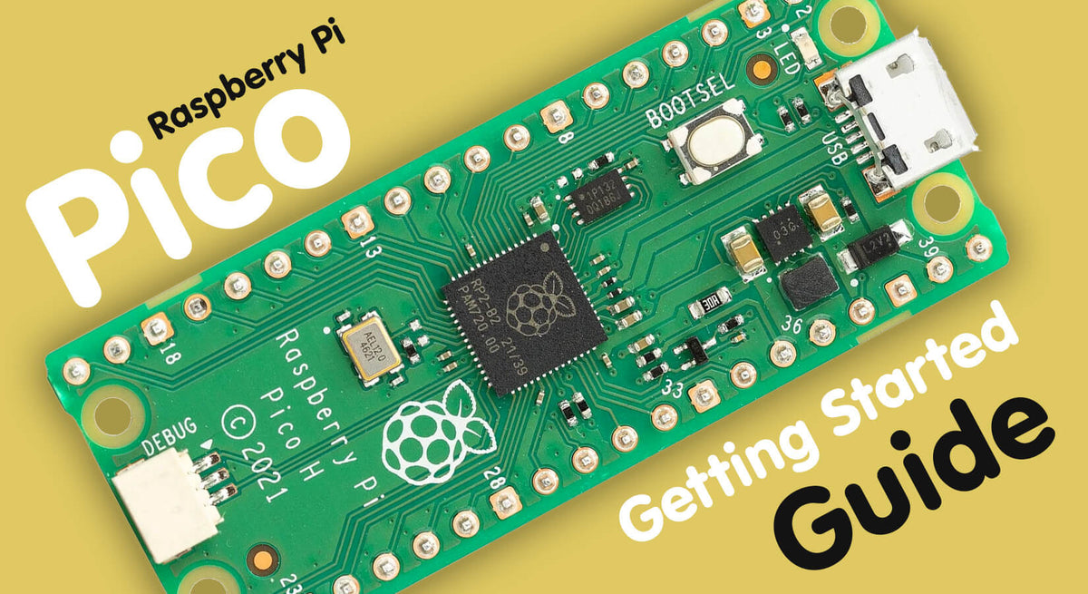
Raspberry Pi Pico Getting Started Guide
If you've just bought your very first Raspberry Pi Pico (or perhaps our superb Raspberry Pi Pico Starter Kit), this easy-to-follow tutorial will help you to get you up and running.
We'll show you around the Raspberry Pi Pico and its various features then explain how to set up popular software to allow you to start coding, with a couple of simple projects to get you started too!
Ready? Let's go!
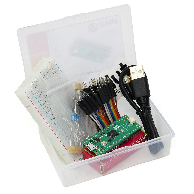
Parts Required
The minimum setup to get started requires a Raspberry Pi Pico and a Micro-USB cable:
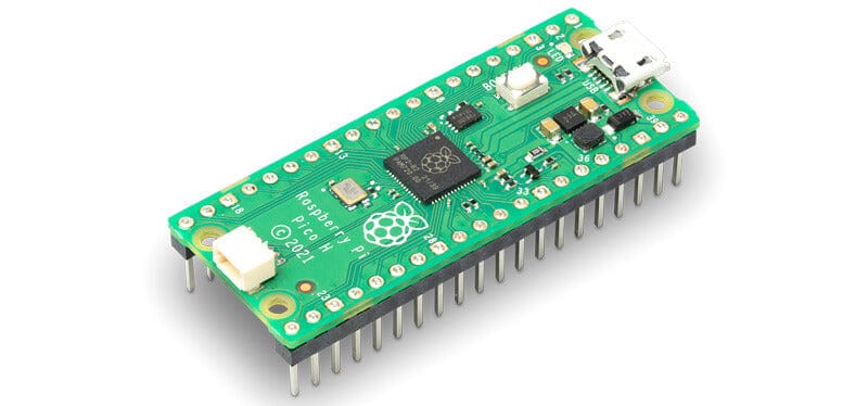
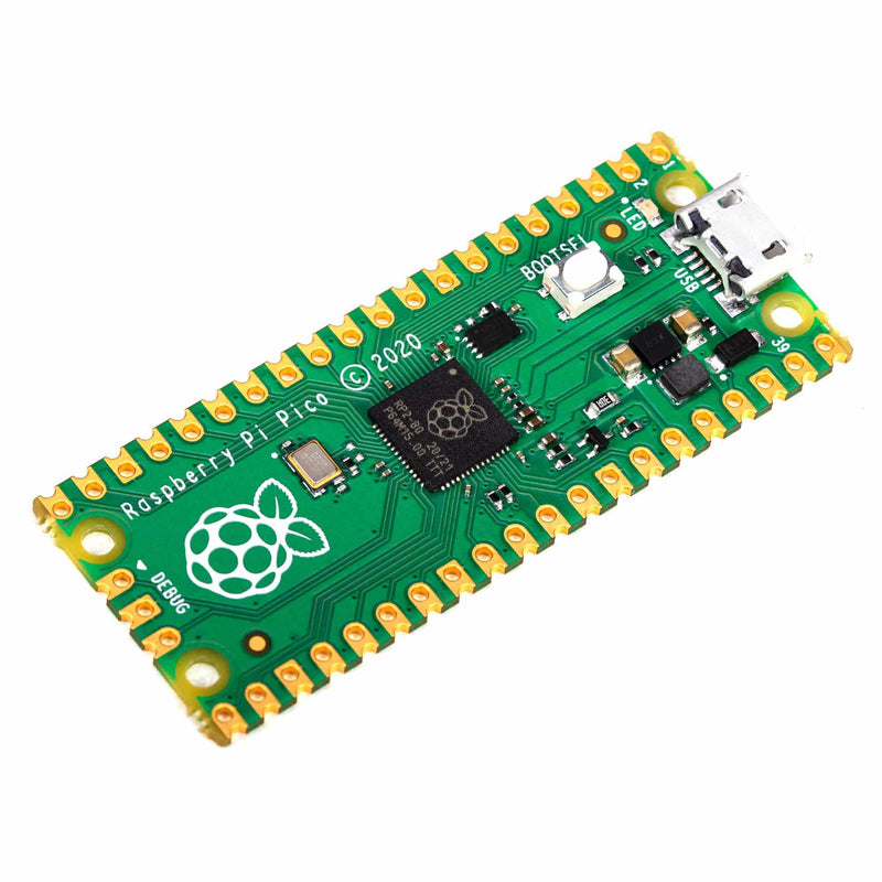
Raspberry Pi Pico
No surprises here - you're going to need a Raspberry Pi Pico! At the time of writing there are three versions of the Pico available, however we recommend the Pico H variant as this comes with pre-soldered headers.
We don't recommended that beginners start with the Raspberry Pi Pico W as you likely won't make use of the wireless features until later down the line.
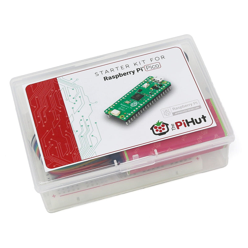
Our Raspberry Pi Pi Pico Starter Kit includes a Pico H, or grab a board from the links below:
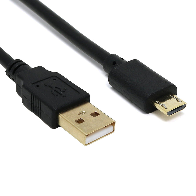
Micro-USB Cable
You'll need a Micro-USB cable to allow your Raspberry Pi Pico to talk to your computer for programming, as well as providing power.
Our Raspberry Pi Pi Pico Starter Kit includes a micro-USB cable, however if you're buying parts separately, you can grab one here.
Optional parts
We're going to be lighting up some LEDs using code as a little starter project. If you've got our starter kit you'll have all the bits you need, however if you're buying parts individually you may need the following items if you want to follow along (many existing makers may already own similar items):
- Breadboard (at least 400-point/half-size)
- 5mm LEDs (300-piece LED kit / Handy 25-pack / Affordable 10-pack)
- 330 ohm resistors (Resistor Kit / Individual pack)
- Jumper wires (Full 120-piece pack / 20-pack)
What is a Raspberry Pi Pico?
The Raspberry Pi Pico is a powerful, flexible microcontroller board from Raspberry Pi - the same nice folks who brought us the Raspberry Pi 4 and Raspberry Pi Zero.
The Raspberry Pi Pico is a different kind of Raspberry Pi though - it's a microcontroller board, not a microcomputer. The brain of the Pico is the RP2040 microcontroller chip, the little black square in the middle.
Whereas you might use a Raspberry Pi 4 (which has an operating system) to play games, write stories and browse the web, the Raspberry Pi Pico is designed for physical computing projects where it can control components such as LEDs, buttons, sensors, motors and even other microcontrollers.
Raspberry Pi Pico Board Features
The Raspberry Pi Pico is pretty tiny, coming in at just 51mm x 21mm - great for embedding into small projects!
One end of the board has a Micro-USB port which, when used with a USB cable, powers the board and allows it to communicate to our computer for programming. The other end has a debug port for debugging (something beginners really won't need to worry about just yet!).
In the middle is the RP2040 chip (the black square) - this is the brains of our board and the first microcontroller chip produced by Raspberry Pi themselves!
All around both sides you'll see lots of pins...so let's talk about those for a moment as you'll be using these a LOT!

Raspberry Pi Pico GPIO Pins
The board has lots of pins around it called GPIO (General Purpose Input Output) pins, which allow you to connect all sorts of components to make projects. These are controlled by code that you write.
A complete map of the Pico H's physical pins is available here. You'll notice lots of labels in lots of different colours, but let's just talk about the main ones you'll be interested in as a new user:
- Light green - These the the basic GPIO pins. We use these to communicate with components such as sensors or LEDs either as an input or an output
- Red - These are your power pins. You'll mostly be using 3V3(OUT) as this provides 3.3V for powering sensors and other parts
- Black - These are your Ground (GND) pins
There are lots of other pin functions available which are represented by the other colours, but let's not worry about those just yet as beginners.
Here's a much simpler version of the Pico pin map with the main pins we're interested in for now:

Raspberry Pi Pico Programming Languages
The Raspberry Pi Pico can use a range of popular programming languages such as C/C++/Arduino and CircuitPython, however the most popular is arguably MicroPython. You'll find the majority of projects and examples on the internet use MicroPython.
MicroPython is an smaller, more efficient version of the Python 3 programming language, designed to be used with microcontroller boards such as the Raspberry Pi Pico. If you've programmed with Python previously, MicroPython will feel very familiar.
Raspberry Pi Pico Setup
Now that we know what the Pico is and how it works, let's get yours set up, running and ready to code! To do this we'll need to download and install some software...
Note: this tutorial is based on using Windows 10/11. This may differ for those using older versions or MacOS. The software we're using is not currently available for Chromebooks (well, not without a lot of messing around at least!)
Software Setup
We’re going to install software called Thonny, which will allow us to program the Pico with MicroPython.
Thonny is a Python IDE. An IDE is an Integrated Development Environment. IDEs help us to write code by giving us lots of helpful features to avoid errors, make our code more readable and lots of other benefits.
So, let's get Thonny! Head over to https://thonny.org/ and look for this little box:

If you hover over the name of the operating system you’re using you should see some options, with a recommended option based on the system you’re using. For us, using a 64-bit version of Windows, it’s recommending the 64-bit version.
Your system may be different, so it’s best to just go with the version the website recommends:

Download the correct version for your computer then open the file to start the installation.
Thonny installs like most programs, and will ask you to accept the license agreement and confirm where to install it. We kept all the options as default and it took just under a minute to install.
Once installed, select ‘Finish’ and then open the program. In Windows 10/11 you can select the Windows Start button and just type in ‘Thonny’. The program should open and look like the example below:

Install MicroPython on the Raspberry Pi Pico
We now need to install the MicroPython firmware on the Raspberry Pi Pico. This gives the Pico the basic software it needs to run MicroPython code that we'll send to it later.
Important Note: You may experience an issue when using the method we have suggested below (SSL errors for example). Give it a try, but if you have trouble installing MicroPython on your Pico, try the other method here instead.
First, plug your Micro-USB cable into the Pico - but don't plug it into your computer yet!
Now locate the little button on top of your Pico. This is the ‘BOOTSEL’ button which, when held in whilst connecting the cable, allows us to install firmware to the Pico.

Hold down that button whilst plugging in the USB cable into your computer’s USB port at the same time. You may see it pop up as a new device on your computer but just ignore that for now.
In Thonny, at the bottom-right-hand corner, you should see something like 'MicroPython (Raspberry Pi Pico)' and a COM port, like the example below (this may vary but it doesn’t matter at this stage). Click on this and you’ll see a few options. Select ‘Install MicroPython…’

You’ll now be presented with some options in a new dialogue box. Use the same options as per the screenshot below, selecting the RPI-RP2 target volume, Raspberry Pi Pico / Pico H variant, and whatever the latest version is available (at the time of writing it was 1.19.1):

Select ‘Install’ and you’ll see a small progress bar whilst it installs. Once complete, select ‘Close’.
Setting up Thonny
Thonny can be used with a range of development boards, so we need to tell Thonny that we are using a Raspberry Pi Pico.
From the top menu, select ‘Run’ then ‘Configure interpreter’:

Now just make sure that ‘MicroPython (Raspberry Pi Pico)' is selected in the first drop-down box, select the available device in the ‘Port’ drop-down, then select ‘OK’.
Tip: If you see multiple options in the Port drop-down box, it just means you have other devices connected to your computer. If you’re not sure which one is the Pico, make a note of what COM ports are showing, disconnect the Pico from the USB port, close the Thonny options box, then try again. Whichever one is now missing was the Pico, so connect it again and select that device next time (it’s a lot easier than disconnecting everything else if you have lots of other devices!)
You should now see a ‘Raspberry Pi Pico’ panel on the left-side of Thonny, and information in the bottom-right 'Shell' panel.
Tip: If you don't see your Pico on the left, try selecting 'View' from the top navigation bar, and selecting 'Files'.

That’s the setup out of the way, we’re ready to code!
Your First Raspberry Pi Pico Program!
Let’s make a very simple program and run it on your Pico.
We’ll tell the Pico to ‘print’ some words (known as a 'string' of text). These words/strings are then 'printed' to the Shell window (the bottom right panel).
The print function is something you’ll use a LOT when programming. It’s a useful tool to see what’s happening with a program, what part of a program is running and can help when debugging projects.
In the top panel (which should be called <untitled> at the moment as we haven't saved it yet), copy/paste or type in enter the following line and then select the green run icon (it looks like a ‘Play’ button) from the menu.
print("This is my Pico talking")
You should now see the following in the Shell window:

You did it! Your first program!
A few things to note:
- Print text strings always sit within inverted commas, within brackets (or parenthesis)
- Letter case is very important with MicroPython and other code languages. Our print is always 'print' and never 'Print'.
Now try changing the text in between the inverted commas - you can write anything you want (why not try the classic "Hello World"?). You can even add multiple print lines one after the other - give it a try!
Light the Pico's Onboard LED
We now know where to write code in Thonny and how to run a program, so let's jump straight into a bit of LED control!
The Pico comes with a little LED onboard, which is attached to one of the RP2040 pins, GPIO25. This pin isn't one of the physical pins available around the edge of the board.
Note: the Pico W has a slightly different pin setup as it uses a GPIO pin on the wireless chip to control the onboard LED. We'll show you how to do this on both boards below.
We can tell our program to turn this pin on and off whenever we like, which is a nice easy first hardware project and can be handy as an indicator for your own projects later on.

Inputs and outputs
Our GPIO pins (the green ones from the pin map) can be set as inputs or outputs. We use inputs when we want something to send signals/voltage in to the Pico, like a button or a sensor, and we use outputs when we want the Pico to send signals/voltage out to something else, like LEDs or buzzers.
We’re going to use an output here, which will send voltage to the onboard LED to light it up.
Imports
Take a quick glance at the first line of the example code below. When we write code in Thonny, a lot of the time we need to add imports at the start.
Imports bring in code from other places (called 'modules' or 'classes' ) that we need to make our program work. Usually these are from built-in modules.
To use the GPIO pins, we always need to import Pin.
The Code - Pico/Pico H version
Take another look at the example below. So, what is it doing?
- The first line imports ‘Pin’ from the 'machine' module on the first line, which simply allows us to use the GPIO pins.
- The second line is setting up one of the pins to allow us to use it in our code. This sets up GPIO25 with the name ‘onboardLED’. We use Pin.OUT at the end there to tell MicroPython to set this pin as an output.
- The third line then finally sets that pin value to ‘1’ which is HIGH (on). 1 is always used for HIGH (on) and 0 is used for LOW (off).
from machine import Pin
onboardLED = Pin(25, Pin.OUT)
onboardLED.value(1)
Copy that code to your top-right panel, then hit the run button. The LED should light up – hooray – you’ve controlled your first physical component!
Now try changing the 1 to a 0 - run the code again and it should turn the LED off.
The Code - Pico W version
If you want to do the same with a wireless-enabled Raspberry Pi Pico W, just change the pin number (25) to 'LED' (including the quotation marks), like this:
from machine import Pin
onboardLED = Pin('LED', Pin.OUT)
onboardLED.value(1)
Light LEDs with the Raspberry Pi Pico
We've mastered the onboard LEDs, so let's now set up a circuit with the LEDs in your starter kit. We'll show you how to wire the circuit and control them with code on your Pico.
First, make sure your Pico is disconnected from the USB cable. You should always do this when amending a circuit.
Breadboards
We're going to be adding components to our breadboard. Breadboards allow you to connect and prototype a circuit without soldering, using wires with pins at the end called jumper wires (sometimes called DuPont wires).
These breadboards have two sets of horizontal channels (red/blue) on both sides. All the red pins are connected, as are the blue (but each side is disconnected from the other). We use these to create 'rails' of connections for us to use, such as Ground (GND) for the blue channel and 3.3V for the red.
The holes in the middle are connected in vertical lanes, with each lane having 5 connected pins either side of the divider. The divider stops both sides connecting together.
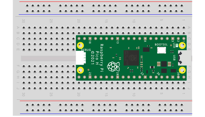
Push your Raspberry Pi Pico fully into your breadboard (so that you can't see the metal pins anymore) as per the image below.
Raspberry Pi Pico LED Circuit
Place the three LEDs into the lower section of the breadboard, 1 hole apart, with the longest leg to the right as seen in the image below.
You won't know which colour is which yet as our kit's LEDs have clear lenses, but that doesn't matter and we'll come back that in a moment. Your breadboard should look like this:

Tip: The short leg is the Cathode (-) and the long leg is the Anode (+).
We now need to add a resistor to limit the current that the LED can draw from our GPIO pins.
Place a resistor between the left leg of each LED and the lower blue channel, like below. We'll be connecting that blue channel to a Ground (-) pin shortly.

Now grab your stash of jumper wires. You need one wire connecting the blue channel to a Ground pin on your Pico – we suggest using physical pin 38 like we’ve done in the diagram below (remember to refer to the Pico pinout if you need a reminder).
You also need to connect the right leg of each LED leg to a GPIO pin. Use GPIO18 (physical pin 24) for Red, GPIO19 (physical pin 25) for Amber, and GPIO20 (physical pin 26) for Green, like the diagram below.
Tip: It doesn't matter what colour jumper wires you use, they all work the same way. In an ideal world we would reserve black for ground connections and red for voltage, but for simple projects it's not essential.

Simple LED Project
We're going to show you a simple bit of code to light each of the LEDs in your kit just to get you started. We’re going to light each LED, wait 5 seconds, then turn them off. To do this we need to use the time module.
The Time Module
The time module allows you to program delays in your code, making it wait for seconds or fractions of seconds before continuing. It’s a fundamental module you’ll use in most of your projects.
The Code
Our code imports pin and also imports time. We then define the pin number for each colour of LED (giving them a sensible name for each) and set them to outputs.
After that it’s a simple case of setting each LED pin HIGH, waiting for 5 seconds using time.sleep(5), then setting them all LOW again.
Here’s the code to copy into Thonny and then run it by hitting the green button:
from machine import Pin
import time

led1 = Pin(18, Pin.OUT)
led2 = Pin(19, Pin.OUT)
led3 = Pin(20, Pin.OUT)

led1.value(1)
led2.value(1)
led3.value(1)

time.sleep(5)

led1.value(0)
led2.value(0)
led3.value(0)
Over to you!
The wonderful world of coding, making, projects and, of course, the Raspberry Pi Pico awaits you!
Be sure to check out the Raspberry Pi website for projects and inspiration, the Raspberry Pi forum Pico section for troubleshooting and ideas, social network user groups for inspiration and support and, as always, search engines are your friend!
Don't forget to also check out our dedicated Raspberry Pi Pico section in the store, full of handy accessories, add-ons, books and more!
We used Fritzing to create the breadboard wiring diagram image


3 comments
Alan
Being sixty something I am concerned about myself getting excited about led s lighting up LoL. Great easy to follow instructions my top tip would be use a Hat compatible GP 10 expander SKU: WAV-20477
purchased from The PIHut makes life easier with large hands.
Being sixty something I am concerned about myself getting excited about led s lighting up LoL. Great easy to follow instructions my top tip would be use a Hat compatible GP 10 expander SKU: WAV-20477
purchased from The PIHut makes life easier with large hands.
The Pi Hut
@Nick – Have you tried the alternative method we suggest for installing MicroPython, where you download the UF2 file and drag it over to the RPI-RP2 folder? Also remember to hold the button down when connecting your USB cable, a lot of people miss that part.
@Nick – Have you tried the alternative method we suggest for installing MicroPython, where you download the UF2 file and drag it over to the RPI-RP2 folder? Also remember to hold the button down when connecting your USB cable, a lot of people miss that part.
nick
ModuleNotFoundError! i have no idear…
ModuleNotFoundError! i have no idear…