 Skip to content
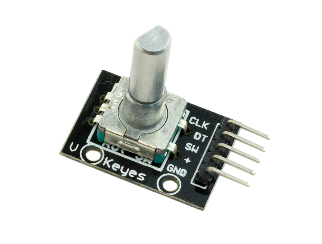
How to use a Rotary Encoder with the Raspberry Pi
In this simple tutorial we will be showing you how to wire up your rotary encoder and how to use some python code to interact with it.
Lets start with a brief explanation of what a rotary encoder is, and how they work!
A rotary encoder is a device that senses the rotation and direction of the attached knob. It works by having 2 internal contacts that make and break a circuit as the knob is turned. As you turn the knob you can feel it "click" indicating that one position has been rotated. If the internal contacts were originally HIGH (or making the circuit) after a single click, they would now both be LOW (breaking the circuit). With a simple bit of logic, you can work out the direction of the rotation (explained in detail below, be sure to check the code first!).
This is what the internals of a rotary encoder look like:

This is what rotating the encode anti-clockwise 1 click looks like:

Let's start with a wiring diagram:

As you can see from the diagram, you need to wire up the rotary encoder as follows:
CLK - GPIO17 (pin11)
DT - GPIO18 (pin12)
+ - 3v3 (pin1)
GND - GND (pin6)
That's it as far as wiring up is concerned. You don't need to worry about any resistors or other compontents, as the encoder has built in 10k Ohm resistors keeping the current to an absolute minimum!
Next, we'll move on to some python code. You can download our example code from our github - https://github.com/modmypi/Rotary-Encoder/
Or download it directly to your Pi using this command in a terminal window:
git clone https://github.com/modmypi/Rotary-Encoder/
This example code is a simple counter. As you rotate the encoder clockwise, the number increase by 1 each "click" and as you rotate it anti-clockwise it decrease by 1 each "click".
Lets dive into the code and see how it works...
cd Rotary-Encoder
nano rotary_encoder.py
Line 4 - Define the GPIO pin for our CLK pin of our rotary encoder
Line 5 - Define the GPIO pin for our DT pin of our rotary encoder
Line 8-9 - Set our GPIO pins to inputs, with a pull down resistor.
Line 11 - Define our counter variable, starting at 0
Line 12 - Get the inital state of our CLK pin
Line 16 - 26 - This is an infinte loop in which we check the states of our CLK and DT pins to first see if the encoder is being rotated, and then to work our if its being rotated clockwise or anti-clockwise
Line 17-18 - So first, we get the current state of our CLK and DT pins
Line 19 - We then compare the current state of the CLK pin againts its previous state. If it's different, the encoder is being rotated so we can then check to see the direction of rotation
Line 20-21 - If our DT pin's state is different to our CLK pin state, then we are rotating in a clockwise direction and therfore need to increase our counter value by 1
Line 22-23 - If our DT pin's state is the same as our CLK pin state, then we are rotating in an anti-clockwise direction and therefore need to decrease our counter value by 1
Line 24 - Simply prints the value of our counter variable
Line 25 - Update our clkLastState variable to match our clkState
Line 26 - Pause the script from 0.01 of a second
The logic for determining the direction of rotation is very simple to code, but not that easy to understand why it works.
So here is a little example of how it works:
For a clockwise rotation
1. CLK and DT are both HIGH
2. CLK goes LOW, DT stays HIGH - clkLastState was HIGH, clkState is LOW (clkState != clkLastState ) so now we can determine direction - dtState is HIGH, clkState LOW, dtState != clkState, +1
3. DT goes LOW, CLK stays LOW - clkLastState was LOW, clkState is LOW - Nothing happens
For a anti-clockwise rotation
1. CLK and DT are both HIGH
2. DT goes LOW, CLK stays HIGH - clkLastState was HIGH, clkState is HIGH - Nothing happens
3. CLK goes LOW, DT stays LOW - clkLastState was HIGH, clkState is LOW (clkState != clkLastState ) so now we can determine direction - dtState is LOW, clkState LOW, dtState == clkState, -1

3 comments
Robert
also as a follow up, what if my encoder has a button, like the middle pin in the first image with the breadboard where can that be connected
also as a follow up, what if my encoder has a button, like the middle pin in the first image with the breadboard where can that be connected
robert
thanks for the guide, i do have a question about connecting more than one, i had 8 i wanted to hook up but i don’t think the pi has that many gpio pins free to do that and still other things, is there perhaps a usb solution out there?
thanks for the guide, i do have a question about connecting more than one, i had 8 i wanted to hook up but i don’t think the pi has that many gpio pins free to do that and still other things, is there perhaps a usb solution out there?
Ted Lloyd
Thanks! Been looking for a good article like this for a couple of months. Using it in a project to control the brightness of a LED.
Thanks! Been looking for a good article like this for a couple of months. Using it in a project to control the brightness of a LED.