Pololu 15V Step-Up Voltage Regulator U3V70F15
Price:
Sale price
£17.30
Stock:
Quantity:
 Skip to content
Cart
Your cart is empty
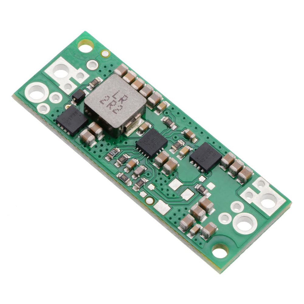


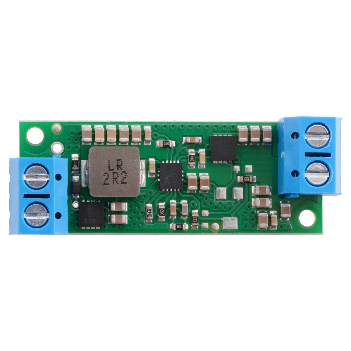
The U3V70x boost (step-up) voltage regulators are high-current, high-efficiency synchronous switching regulators that generate higher output voltages from input voltages as low as 2.9V - this particular model (U3V70F15) provides a 15V output voltage with a minimum input voltage of 2.9V (typical max input current* 7A).
* Actual achievable continuous current is a function of input voltage and is limited by thermal dissipation. See the output current graphs on the product pages for more information.
The regulators actively limit the instantaneous input currents to 10A, and the input current can typically be as high as 8A for several seconds before the thermal protection activates. Input currents of around 6A can typically be maintained for many minutes without triggering thermal shutdown, though the actual performance depends on the input and output voltages as well as external factors such as ambient temperature and airflow.
For boost regulators, the output current equals the input current times the efficiency times the ratio of VIN to VOUT, so the more you are boosting, the lower the maximum output current will be (see the Typical efficiencies and output currents section below for performance graphs).
These regulators feature a variety of built-in protections, including reverse voltage protection to keep your load safe in the event power is accidentally connected backwards, and unlike most boost regulators, these units offer a true shutdown option that turns off power to the load (with typical boost regulators, the input voltage will pass directly through to the output when they are disabled).
Warning: During normal operation, this product can get hot enough to burn you. Take care when handling this product or other components connected to it.

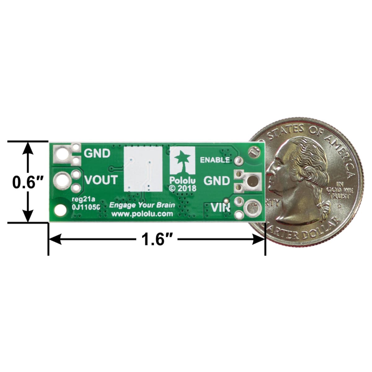
The input voltage, VIN, must be at least 2.9V and should not exceed the output voltage, VOUT. (If VIN is higher than VOUT, the higher input voltage will show up on the output, which is potentially dangerous for your connected load and could also damage the regulator.)
The regulator is enabled by default: a 100 kΩ pull-up resistor on the board connects the ENABLE pin to reverse-protected VIN. The ENABLE pin can be driven low (under 0.4 V) to turn off power to the load and put the board into a low-power state. The typical no-load quiescent current is less than 1 mA (see the quiescent current graph below for more details).
The efficiency of a voltage regulator, defined as (Power out)/(Power in), is an important measure of its performance, especially when battery life or heat are concerns. As shown in the graphs below, the U3V70x regulators have an efficiency of 80% to 95% for most combinations of input voltage, output voltage, and load.
The maximum achievable output current is approximately proportional to the ratio of the input voltage to the output voltage. Additionally, the maximum output current can depend on other factors, including the ambient temperature, airflow, and heat sinking. The graph below shows the typical maximum continuous output currents these regulators can deliver at room temperature with no forced airflow or heat sinking.

Warning: During normal operation, this product can get hot enough to burn you. Take care when handling this product or other components connected to it.
When connecting voltage to electronic circuits, the initial rush of current can cause damaging voltage spikes that are much higher than the input voltage. In our tests with this family of regulator connected with typical power leads (~30″ test clips), we found that input voltages above 17V caused voltage spikes in excess of 20V, which could damage the regulator.
Lower input voltages caused smaller spikes that could still be problematic for boost regulators operating with the input voltage close to the set output voltage, since input voltages above the set output voltage will propagate to the output and could damage circuits being powered by the regulator. A large electrolytic capacitor (33 μF is a good starting point) can be added close to the regulator between VIN and GND to help suppress these spikes.
More information about LC spikes can be found in our application note, Understanding Destructive LC Voltage Spikes.
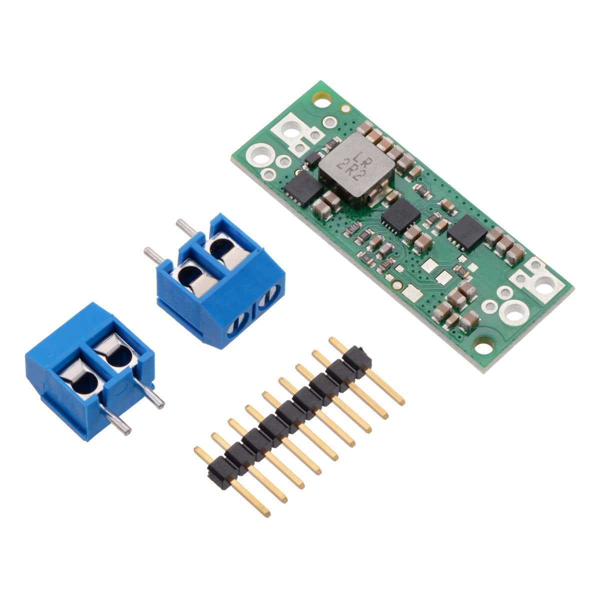
Along with the regulator, you will receive a 9-way 0.1" header strip and two terminal blocks.
This regulator offers several options for making electrical connections. The nine smaller through-holes on the ends of the board are arranged with a 0.1″ spacing for compatibility with solderless breadboards, connectors, and other prototyping arrangements that use a 0.1″ grid. The included 0.1″ male header can be broken or cut into smaller pieces as desired and soldered into these smaller through-holes.
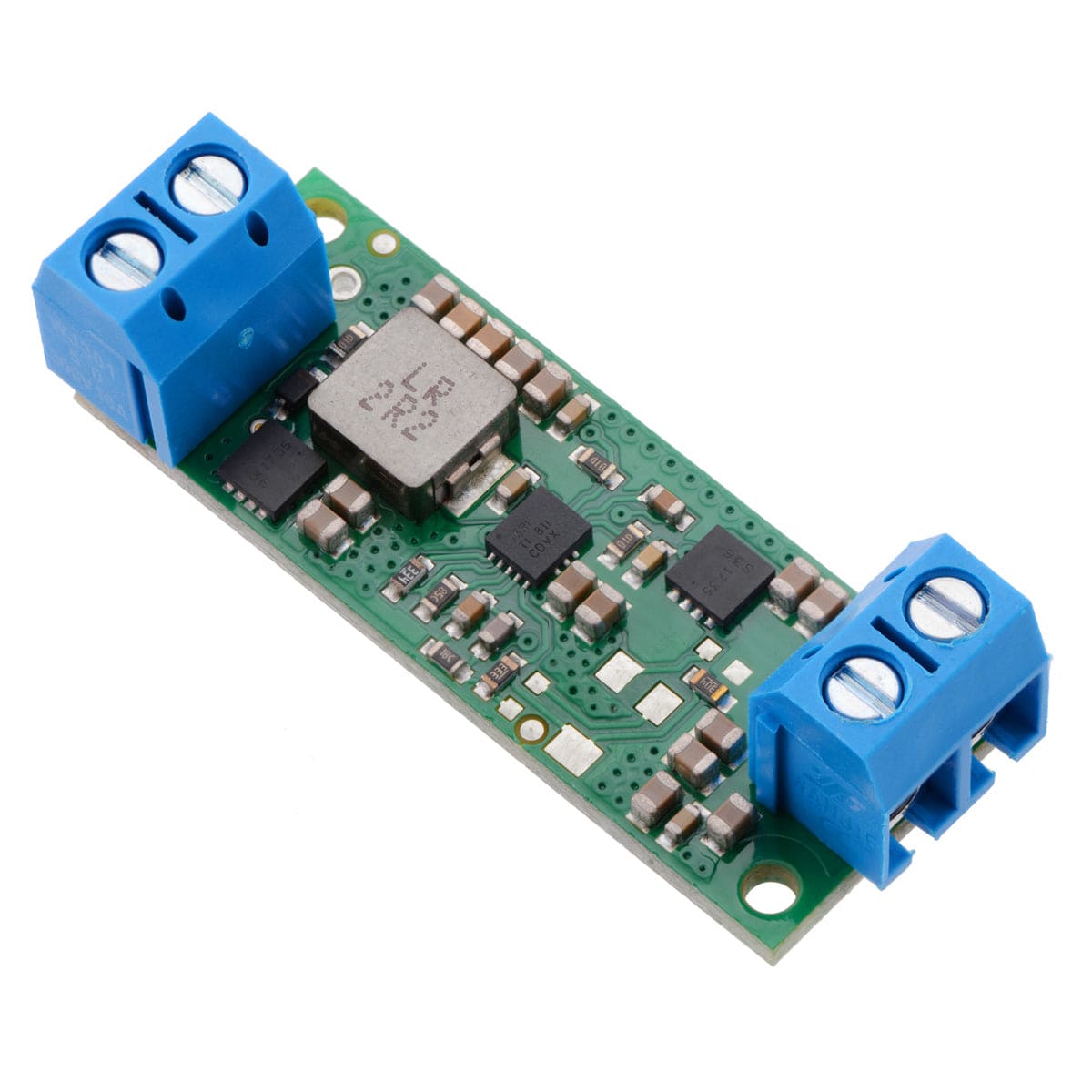
Alternatively, the included terminal blocks can be soldered into the larger holes to allow for convenient temporary connections of unterminated wires (see our short video on terminal block installation). You can also solder wires directly to the board for the most compact installation.
Your payment information is processed securely. We do not store credit card details nor have access to your credit card information.
