Adafruit Infrared IR Remote Receiver - STEMMA JST PH 2mm
Price:
Sale price
£4.80
Stock:
Coming Soon
 Skip to content
Login / Signup
Cart
Your cart is empty
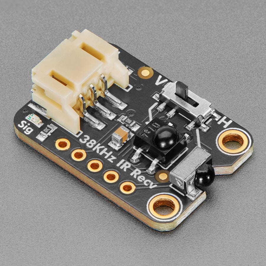
A year ago we designed a high-current-output Infrared Transmitter STEMMA which makes it easy to create high-powered IR LED blasters. Now we've sat down to design the other side, the super sensitive wide-range Adafruit Infrared IR Remote Receiver with two selectable IR receiver chips.
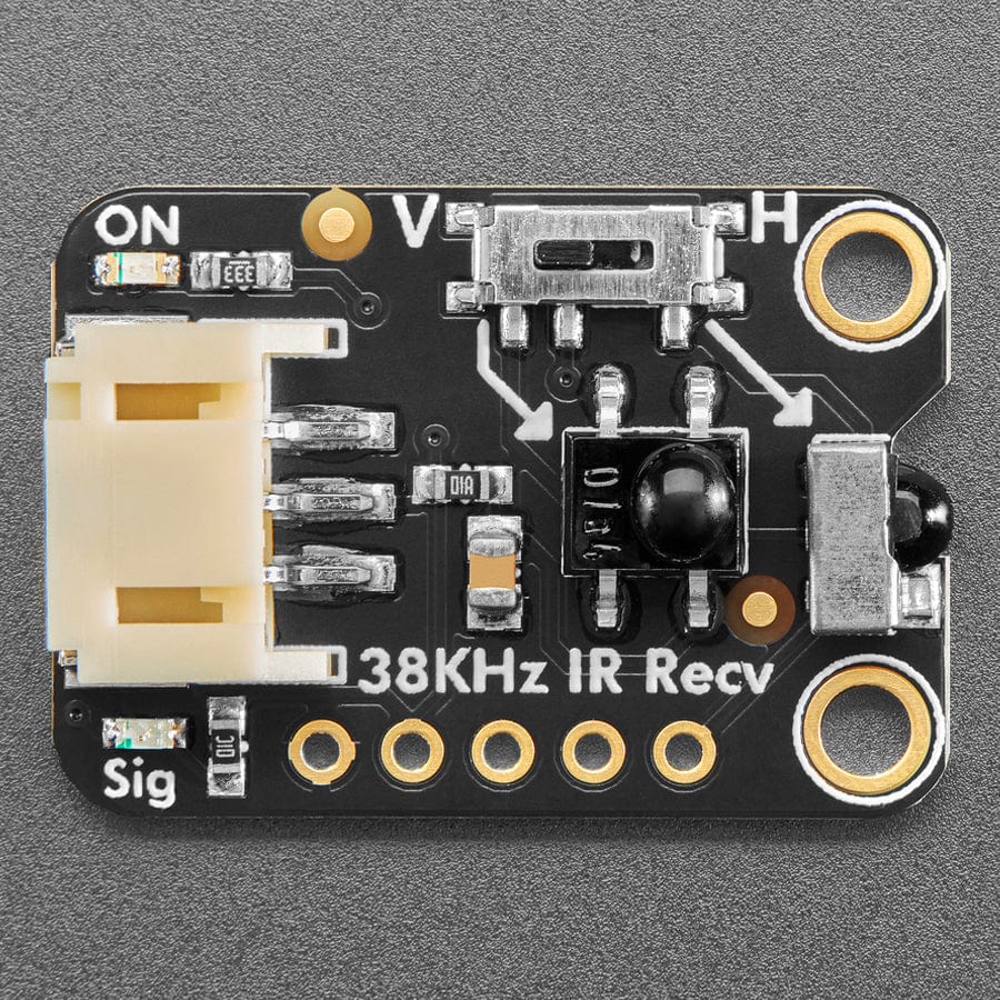
We found plenty of 38KHz receiver sensors that would work nicely on this breakout board - but when it came to choosing one that was vertical or horizontal we just couldn't make up our mind...so why not both? We've placed one on the end and one in the middle, and a slide switch to select which one you want to read the signal from. We can't just tie the outputs together because they'd 'fight' each other and give incoherent output - but if you're willing to solder two wires, it's possible to read each one independently thanks to labelled breakout pads.
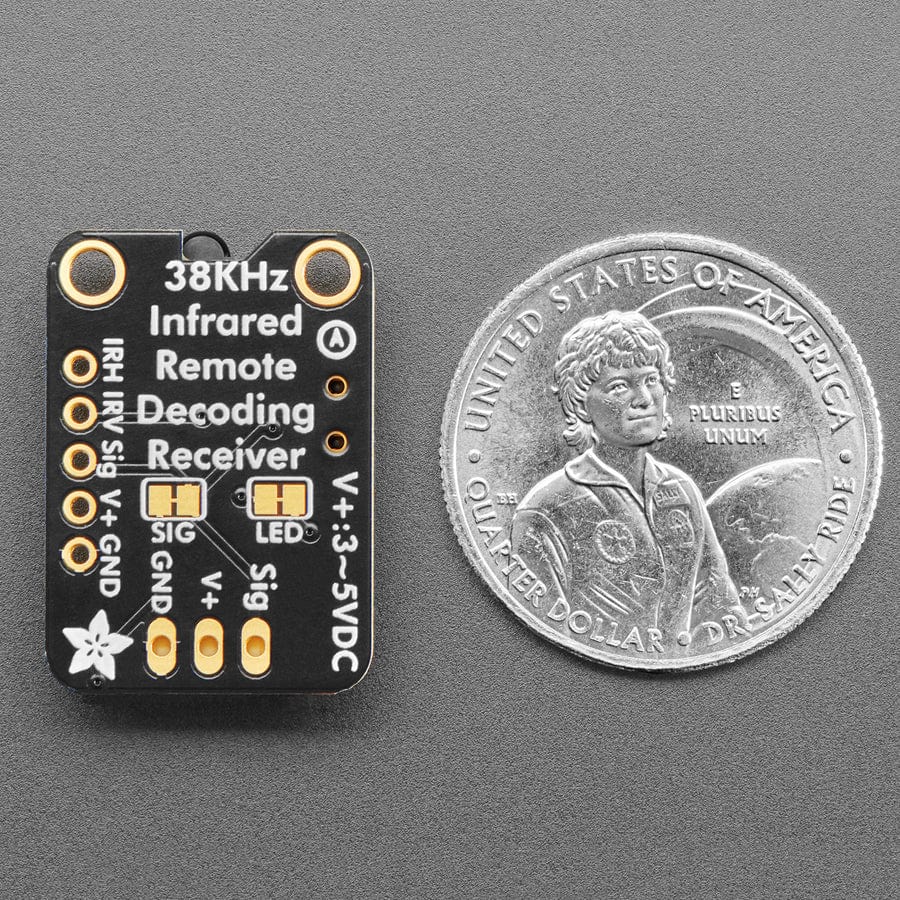
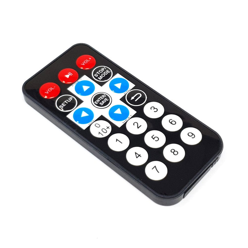
Usage is simple: Power the board by connecting V+ and ground to 3~5VDC, point a 38KHz remote control at the sensors and press some buttons. The demodulated IR envelope is piped out the Signal pin into your microcontroller which will then need to decode it. To make usage really easy, we have a green 'power good' LED and a red 'signal' LED. When IR remote signals are read by the onboard sensors, the red LED will blink to let you know.
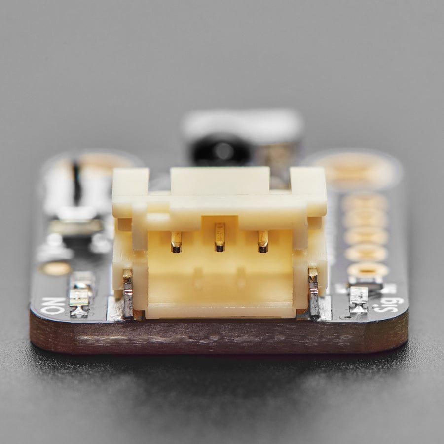
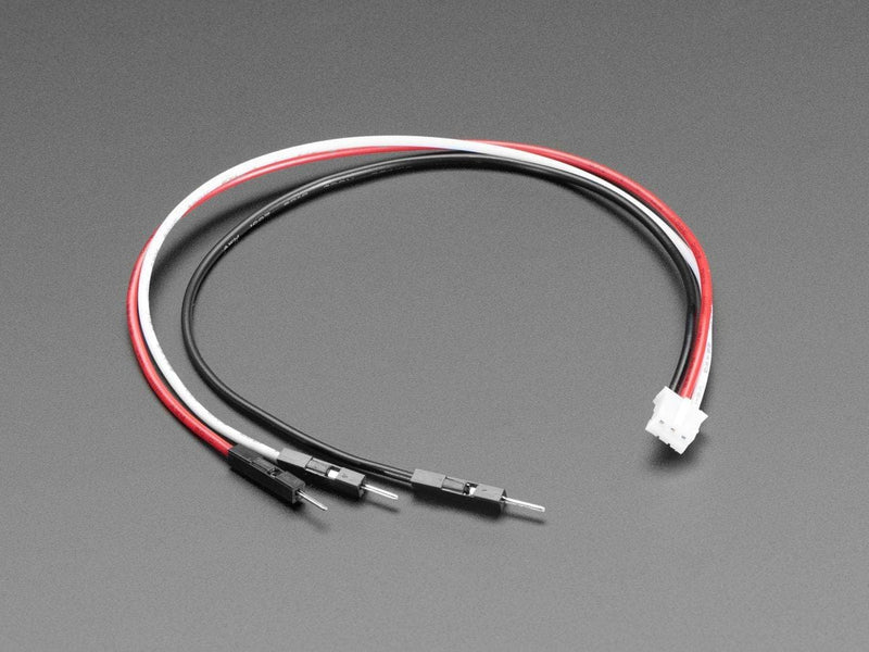
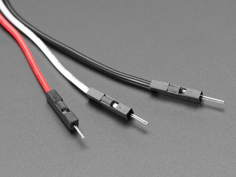
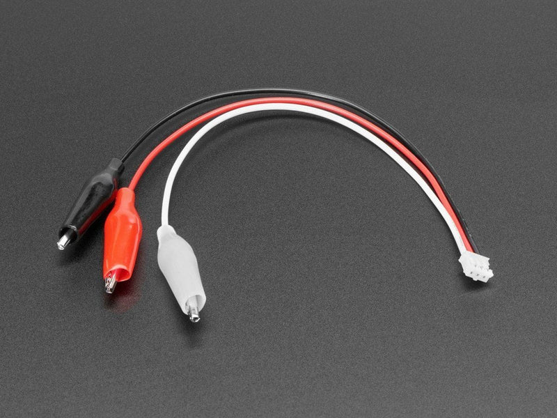
This board will work nicely for a variety of IR remote receiving projects, and with mounting holes and a cable, a lot easier to mount in enclosures and on devices. Using a 2mm pitch STEMMA JST PH cable with headers or alligator clips on the end, you can easily wire this board without any soldering.
Note that this board is specifically for receiving 38KHz IR remote control signals - it isn't going to work for proximity/distance sensing or other frequency signals. The signal must be read by a microcontroller that has pulse-input reading capabilities - basically just check that it supports common IR Receiver connectivity and decoding. Sometimes you need to use special code or pins.
Each STEMMA board is a fully assembled and tested PCB but no cable. No soldering is required to use it, but you will need to pick up a 2mm pitch, 3-pin STEMMA JST PH cable. Alternatively, if you do want to solder, there's a 0.1" spaced header for power/ground/signal.
Your payment information is processed securely. We do not store credit card details nor have access to your credit card information.