Four Relays Four Inputs 8-Layer Stackable Card for Raspberry Pi V4.0
Price:
Sale price
£44.40
Stock:
Quantity:
 Skip to content
Cart
Your cart is empty
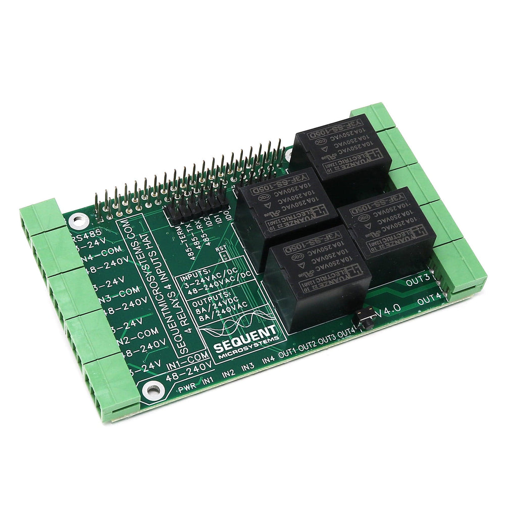


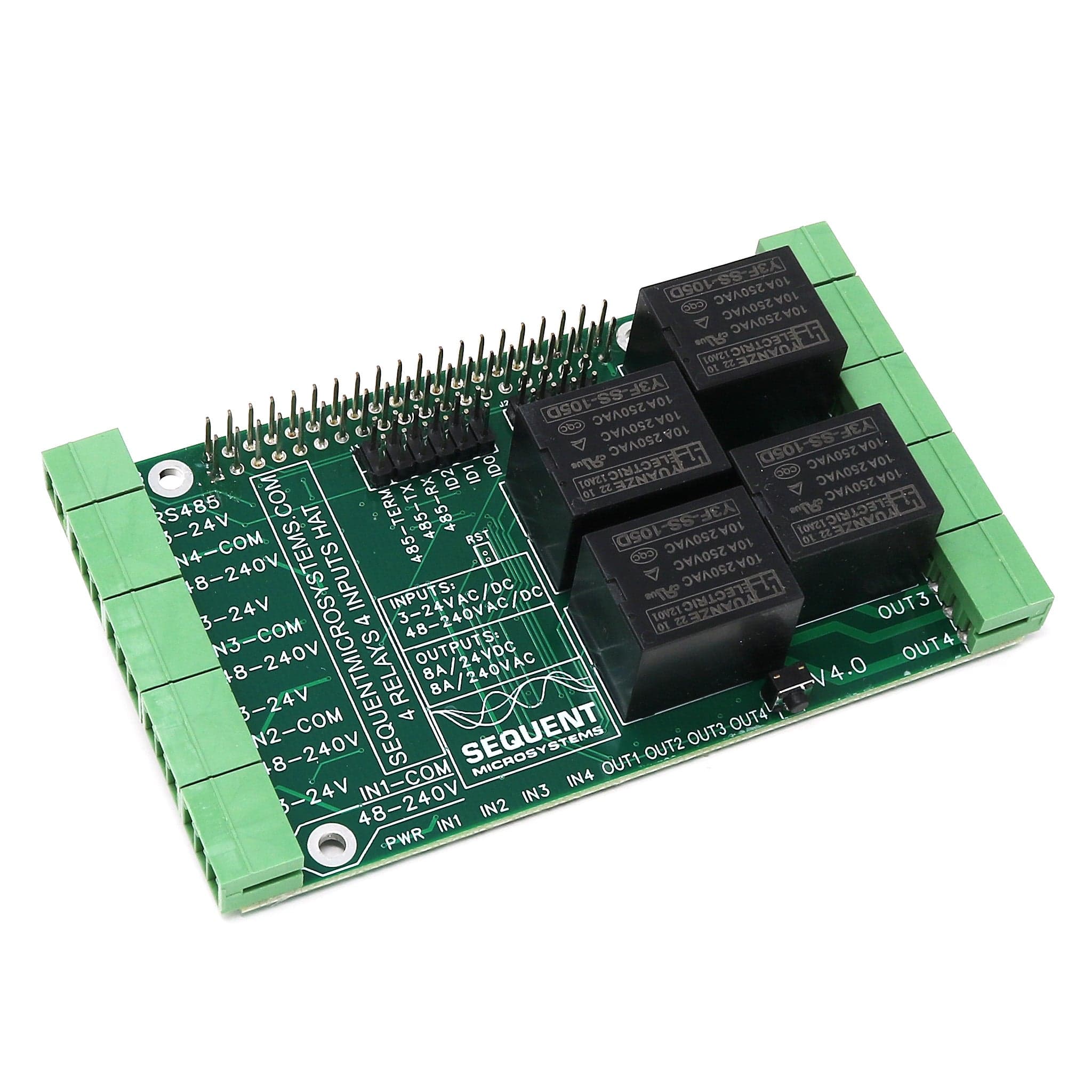
Four heavy-duty relays plus four universal inputs for your Raspberry Pi!
Drive 8A/240VAC loads and read 3V to 240V, AC or DC, Opto-isolated inputs for all your Home or Industrial Automation Projects.
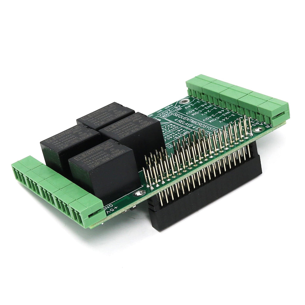
A perfect add-on to your project when you have to control a large number of heavy-duty AC loads and/or you have to read wide-range inputs. Stackable to 8 layers, the card can add up to 32 relays to each Raspberry Pi in a very compact form factor. In addition, you can read up to 32 opto-isolated inputs.
Pluggable connectors make this card easy to use when multiple cards are stacked up. All relays have Normal Open and Normal Close contacts and can switch up to 8A/240VAC.
The optically isolated universal inputs can read AC or DC signals from 3V to 240V. The input connectors have a low voltage port that can read signals between 3V and 24V, and a high voltage port that can read signals between 48V and 240V.
For any technical questions about this product please email support@sequentmicrosystems.com
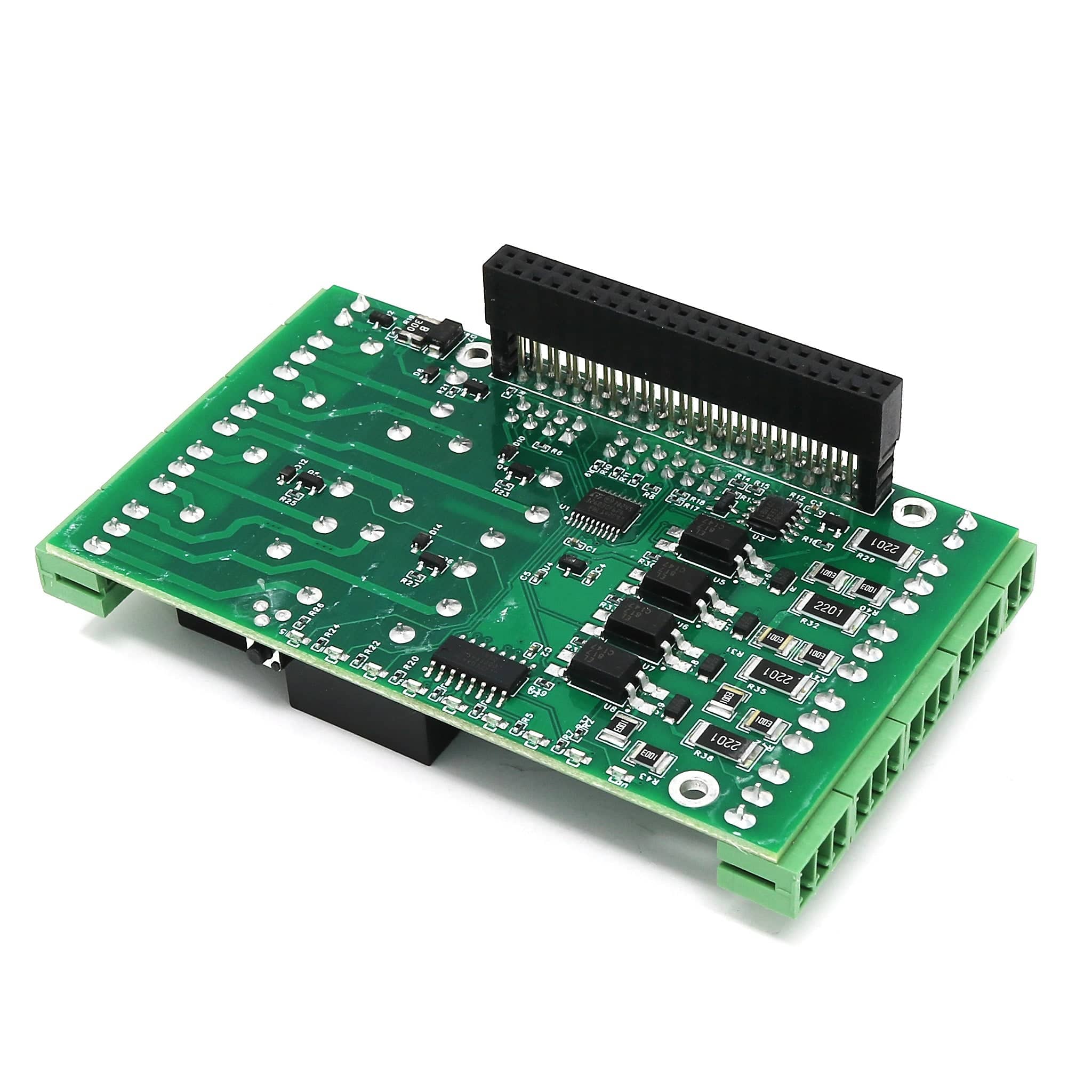
The 4.0 release of the card replaced the I/O expander with a local processor. This enhancement allowed us to add several new features:
Power Requirements
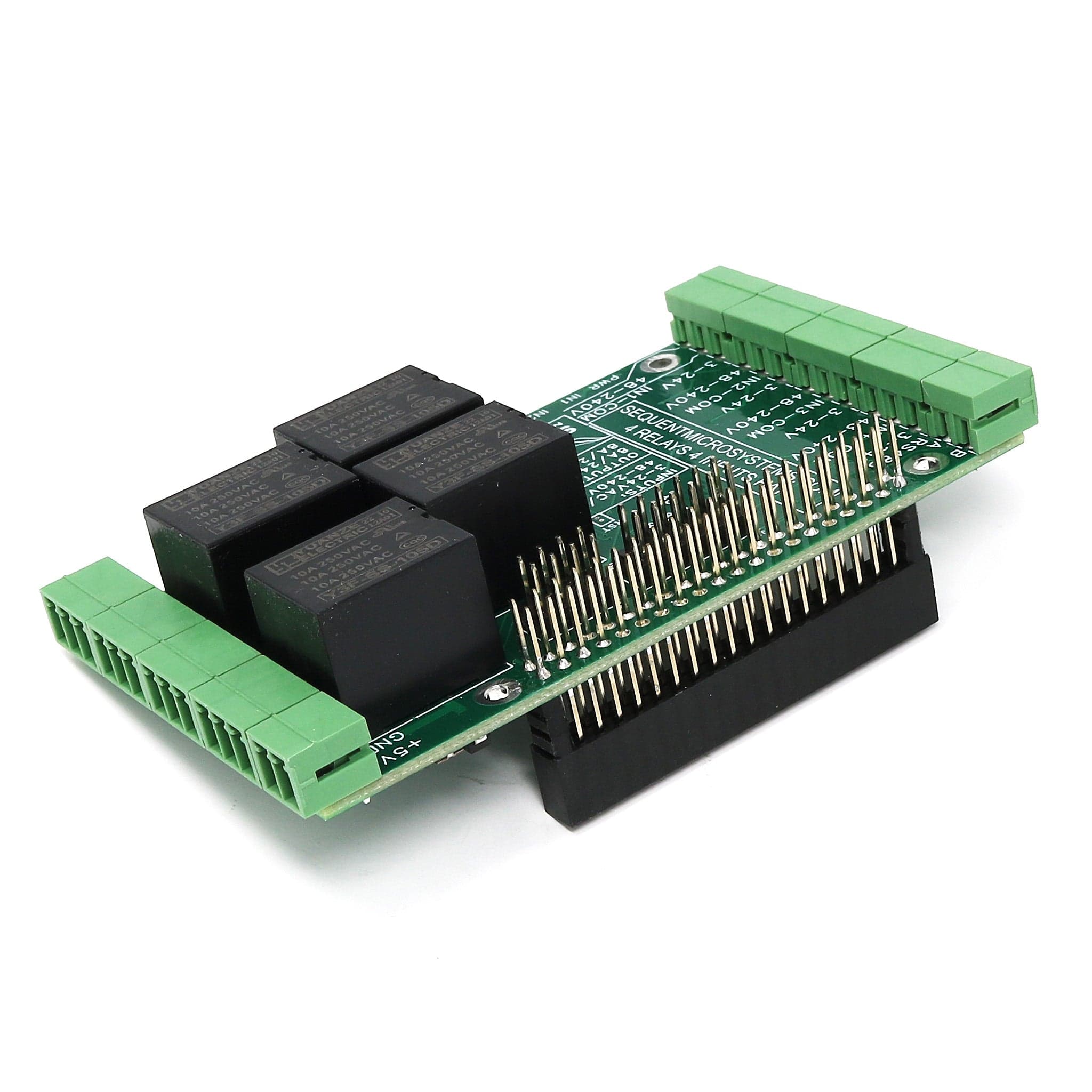
The card needs 5V to operate and can be powered from Raspberry Pi or from its own 2-pin pluggable connector.
The relay coils are also powered from the 5V. The card draws 10mA with all relays off. Each relay needs about 80 mA to turn on. If power is applied to the 2-pin pluggable connector, no other power supply is needed for the Raspberry Pi.
Stacking Multiple Cards
Up to eight cards can be stacked on your Raspberry Pi. Each card is identified by jumpers you install to indicate the level in the stack. Cards can be installed in any order. A three-position jumper selects the stack level. For your convenience, two jumpers are provided with each card.

Reverse Power Supply Protection
The board is protected from an accidental reverse power supply with a 5.8A, 39 mOhm MOSFET which breaks the ground line if reverse power is applied.
Reset Pushbutton
Shutting down the Raspberry Pi by turning off the power can result in SD card failure. To prevent this, a shutdown command needs to be used before power cut-off. But this requires a monitor, keyboard and mouse connected to the Pi.
A momentary push-button installed at the edge of the board provides a convenient way to shut down the Raspberry Pi. The button is routed to pin 37 (GPIO 26). You need to write a script that monitors this pin, and if pressed for more than the desired time, issues the shut-down command.
Compatability
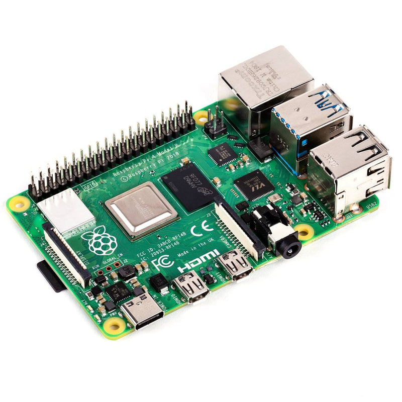
The card is compatible with all 40-pin Raspberry Pi versions from the Pi Zero to the Raspberry Pi 5. All stacked cards share the I2C bus using only two of the Raspberry Pi’s GPIO pins to manage all eight cards. This feature leaves the remaining 24 GPIOs available for the user.
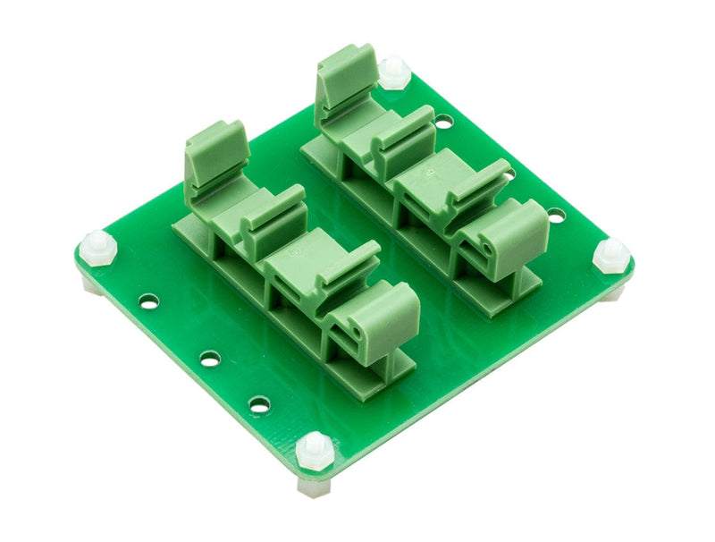
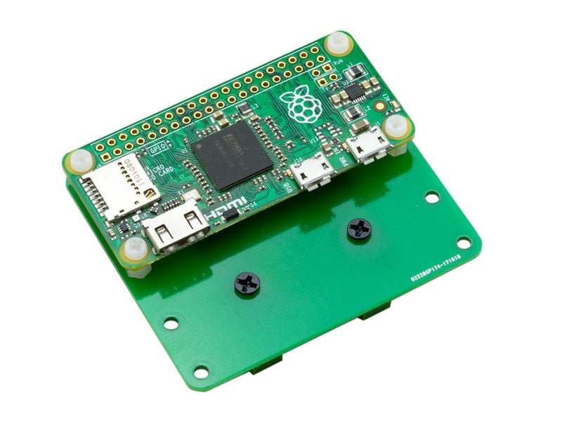
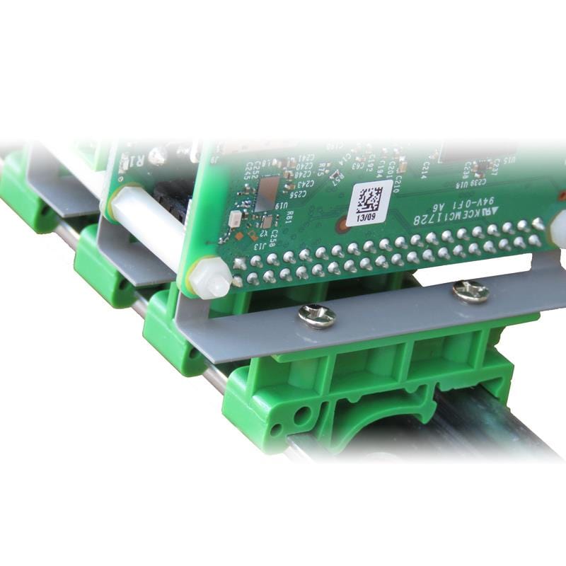
DIN Rail Mounting
The card can be installed parallel on a DIN-Rail using the DIN-Rail Kit Type 1, or perpendicular using the DIN-Rail Kit Type 2.
Software Interfaces
You can write your own application using the Command Line or Python Libraries provided. A usage example for the python library can be found in the tests.py file in the repository. No programming is required if you use the Node-Red nodes we supply. You can drag and drop the functional blocks to design your application. Examples are also provided.
All downloads can be found here.
Relay Self Test
The card can be tested before installation by running a simple command from the command line. The card will cycle each relay on and off at 0.5 second intervals. The clacking noise of the relays and the lighting of the LEDs will assure that all relays are functioning.
RS485/MODBUS Port
A standard RS485 transceiver permits the Raspberry Pi to communicate using any protocol including MODBUS, PROFIBUS, camera PTZ control, etc.
The transceiver can be driven either from the Raspberry Pi serial port, or directly from the local processor.
Install the jumpers 485-TX and 485-RX on connector J3 to drive the port from Raspberry Pi. Install the terminator jumper 485-TERM if the card is last on the RS485 chain.
Raspberry Pi not included
Your payment information is processed securely. We do not store credit card details nor have access to your credit card information.