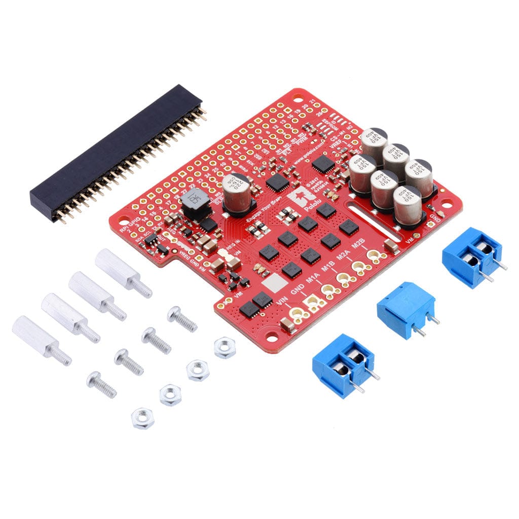
Pololu Dual G2 High-Power Motor Driver for Raspberry Pi
Version:24v14
Price:
Sale price
£72
Stock:
Quantity:
 Skip to content
Cart
Your cart is empty
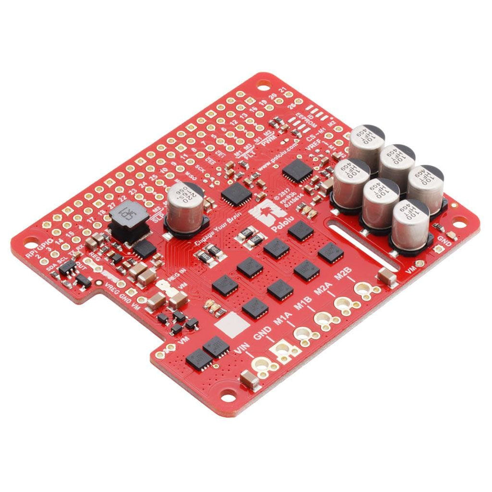


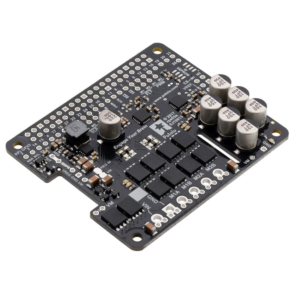


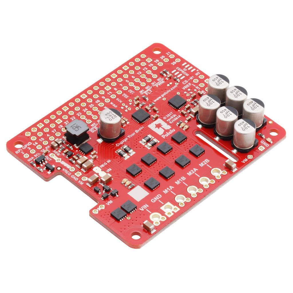
This add-on board makes it easy to control two high-power DC motors with a Raspberry Pi.
Its twin discrete MOSFET H-bridges support a wide operating voltage range and are efficient enough to deliver a continuous current without a heat sink. The drivers offer basic current limiting functionality, and they accept ultrasonic PWM frequencies for quieter operation. The default pin mappings make it easy to get started, but they can be customized for more specialized applications.
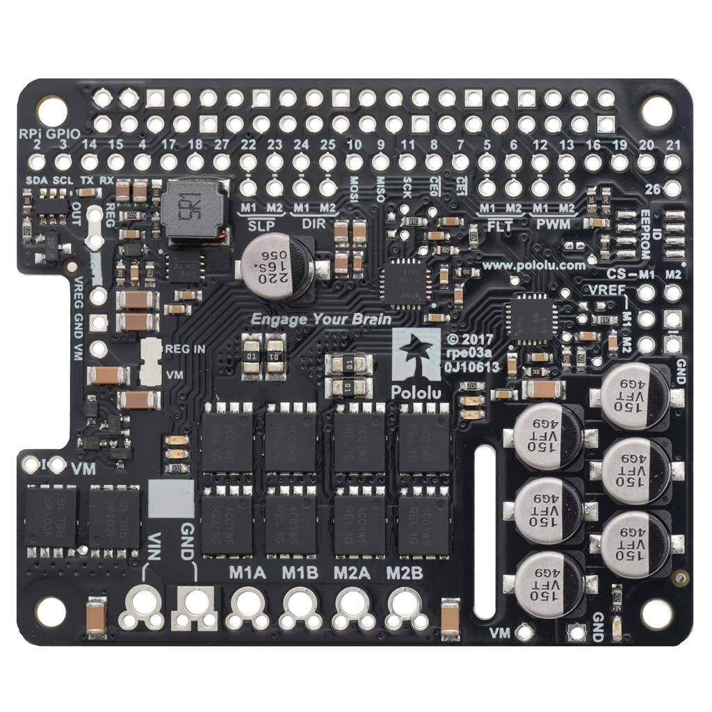
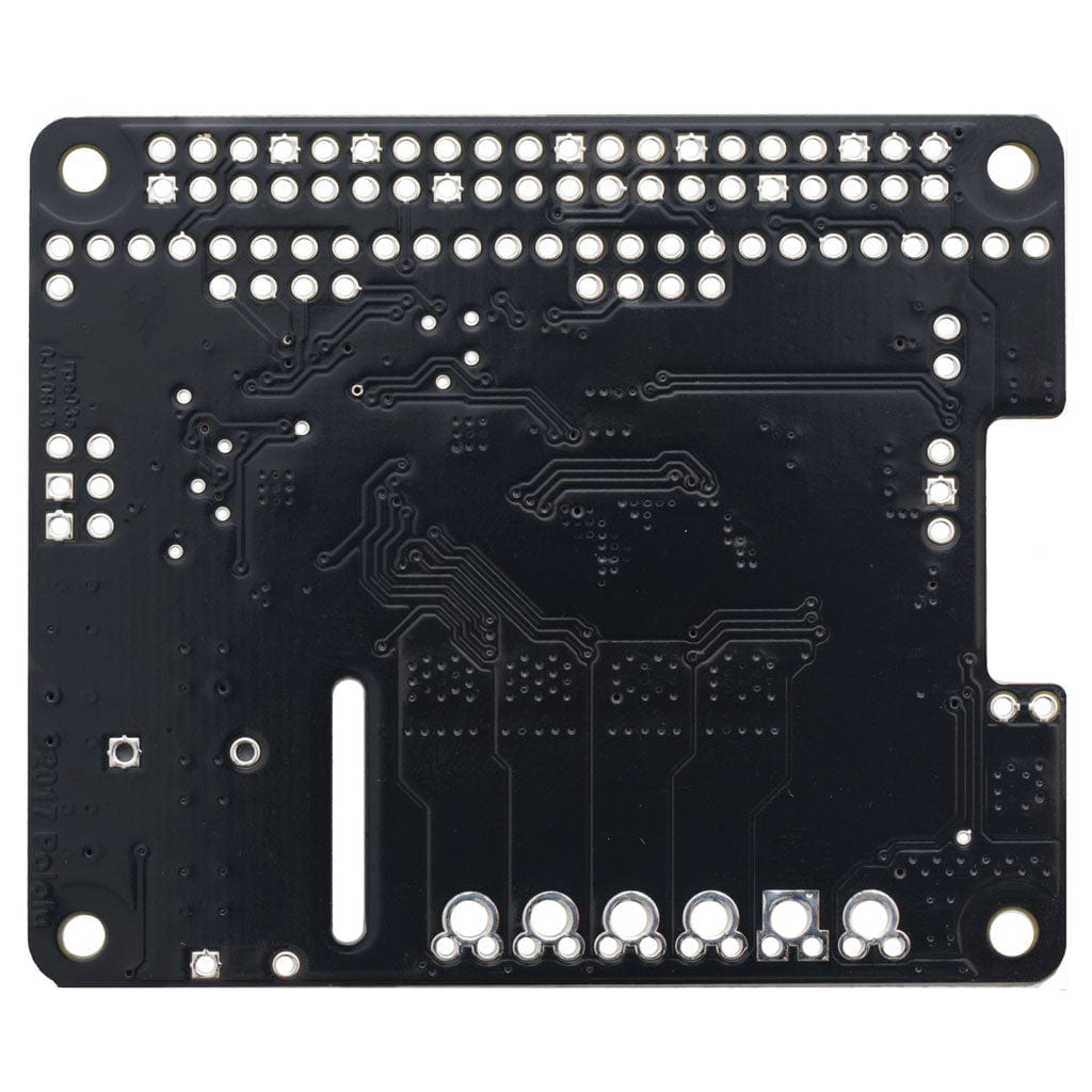
These G2 dual high-power motor drivers are add-on boards for the Raspberry Pi, featuring pairs of discrete MOSFET H-bridges designed to drive two large brushed DC motors. They are designed to mount on and plug into compatible Raspberry Pi boards (any with 40 GPIO pins).
Three versions are available so you can pick the one with the appropriate operating voltage range and output current capabilities for your project (select above):

* 40 V if regulator is disconnected
The minimum operating voltage for all four versions is 6.5 V, while the maximum operating voltages are given in the above table. The board also includes an integrated 5 V, 2.5 A switching step-down regulator that can be used to power the Raspberry Pi it is plugged into, enabling operation from a single power supply.
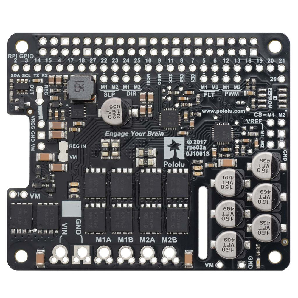
The driver’s default configuration uses six GPIO pins to control the motor drivers, making use of the Raspberry Pi’s hardware PWM outputs, and it uses two additional pins to read status outputs from the drivers. However, the pin mappings can be customized if the defaults are not convenient, and pins for current sensing and limiting are accessible on the board for more advanced applications.
Note that this motor driver add-on is designed specifically for newer versions of the Raspberry Pi with 40-pin GPIO headers. The board matches the Raspberry Pi HAT (Hardware Attached on Top) mechanical specification, although it does not conform to the full HAT specifications due to the lack of an ID EEPROM. (A footprint for adding your own EEPROM is available for applications where one would be useful; pull-ups on SDA, SCL, and WP are provided.) It is not practical to use this expansion board with the original Raspberry Pi Model A or Model B due to differences in their pinout and form factor.
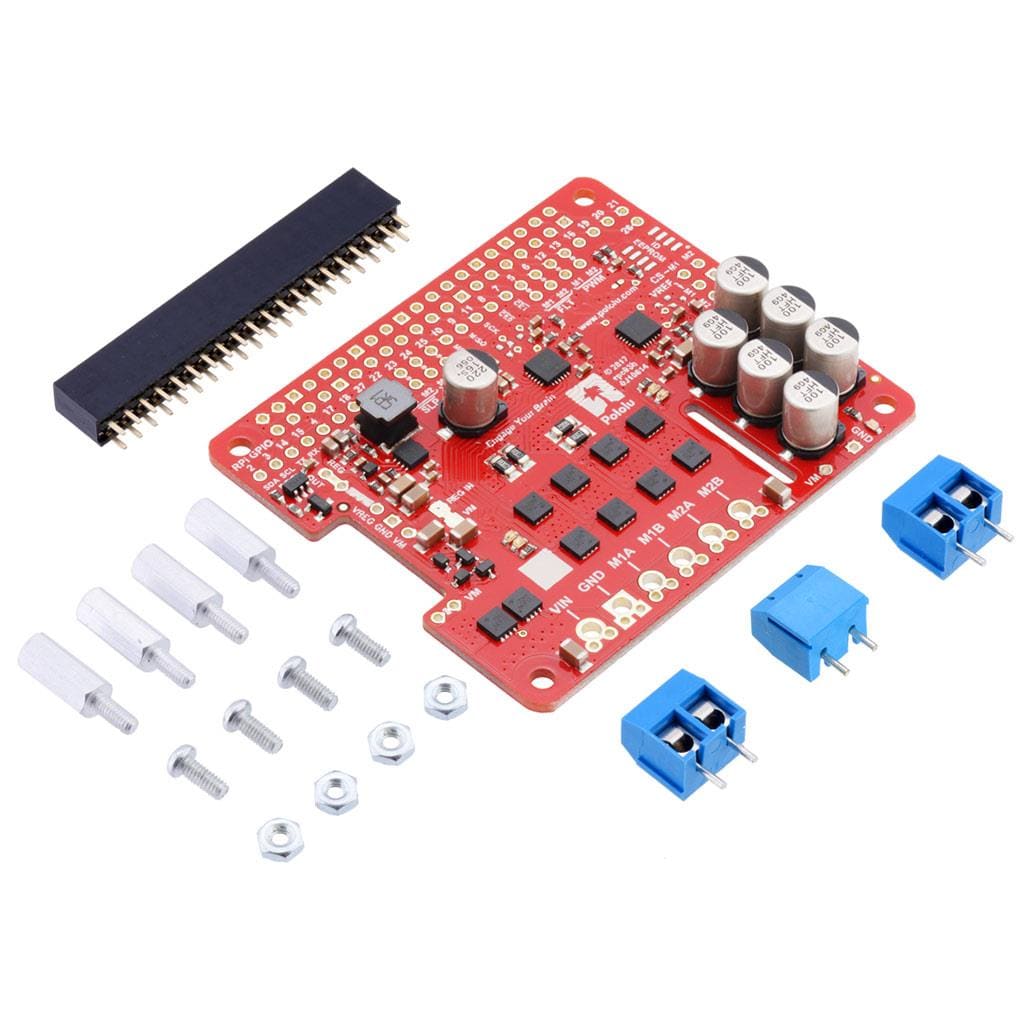
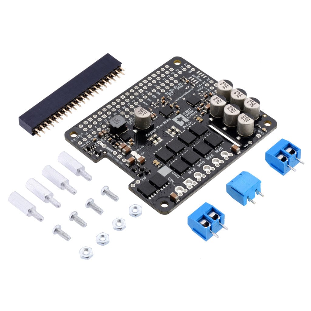
The following through-hole connectors and mounting hardware are included with the board, which ships with its surface-mount components populated:
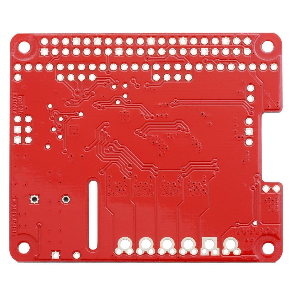
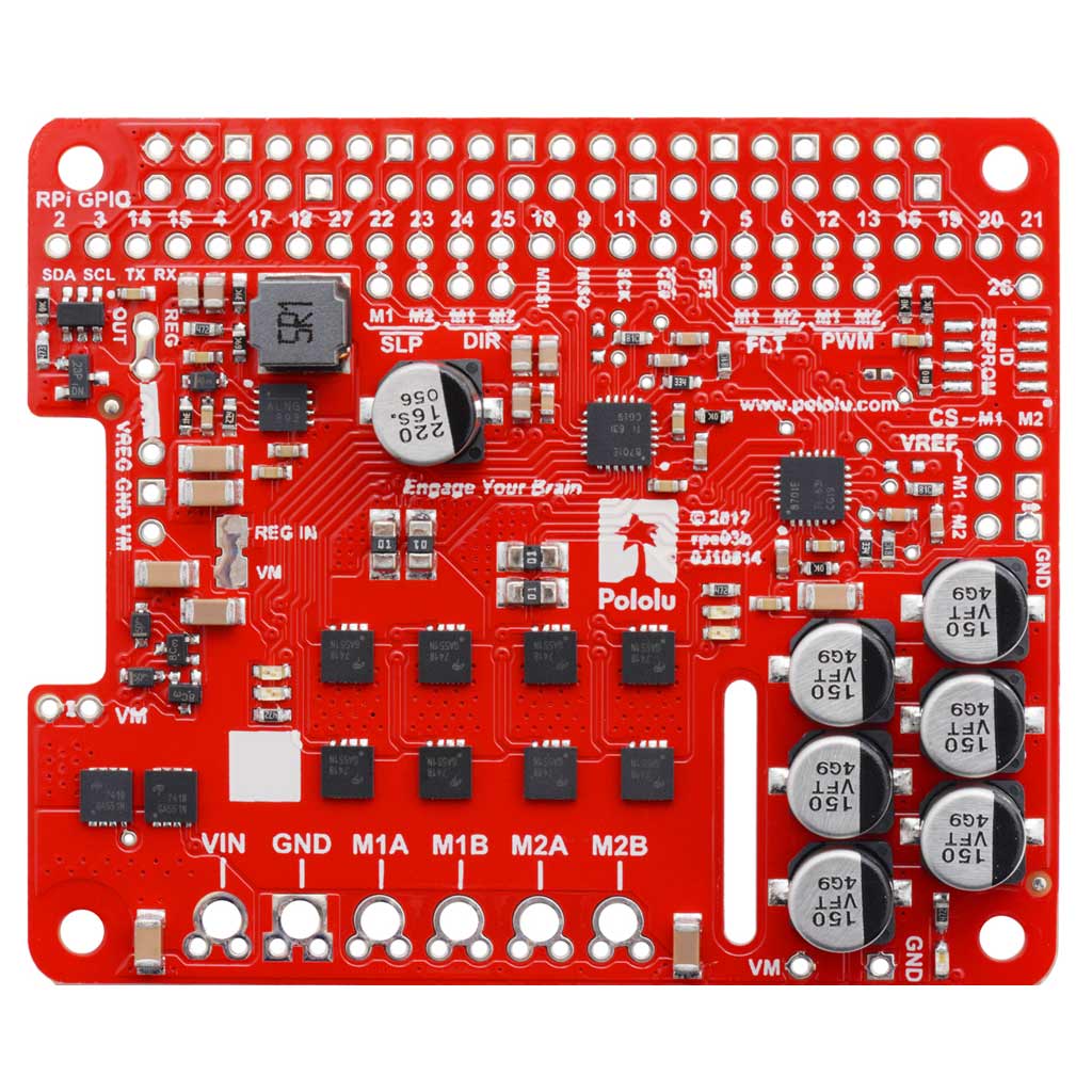
The 2×20-pin 0.1″ female header should be mounted to the bottom of the board (the side opposite the surface-mount components). Once soldered, this header is used to connect the board to the Raspberry Pi’s 40-pin GPIO header. Alternatively, if you want to continue to have access to the Raspberry Pi’s 40 GPIO pins while the motor driver board is plugged in, you can install a stackable 2×20-pin female header (not included) instead.
You can solder the terminal blocks to the six large through-holes to make your motor and motor power connections, or you can solder a 0.1″ male header strip (not included) into the smaller through-holes that border these larger holes. Note, however, that the terminal blocks are only rated for 16 A, and each header pin pair is only rated for a combined 6 A, so for higher-power applications, thick wires should be soldered directly to the board.
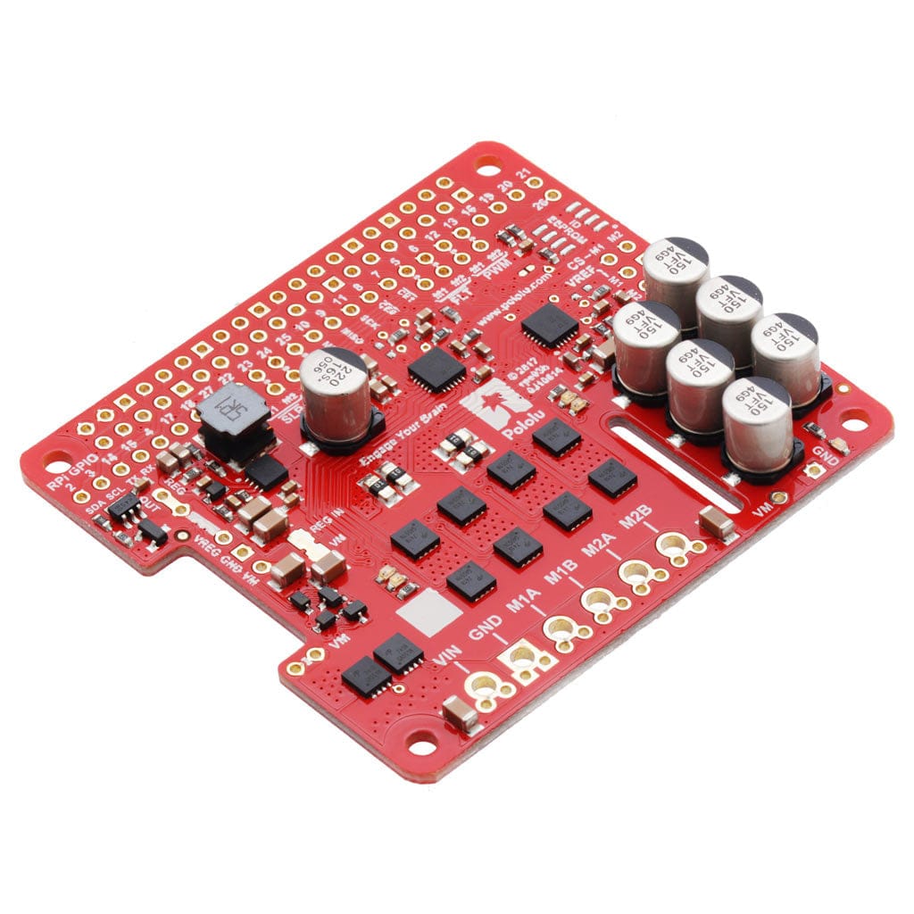
The motor driver includes six 100 μF or 150 μF electrolytic power capacitors, and there is room to add additional capacitors (e.g. to compensate for long power wires or increase stability of the power supply). Additional power capacitors are usually not necessary, and no additional capacitors are included with this motor driver.
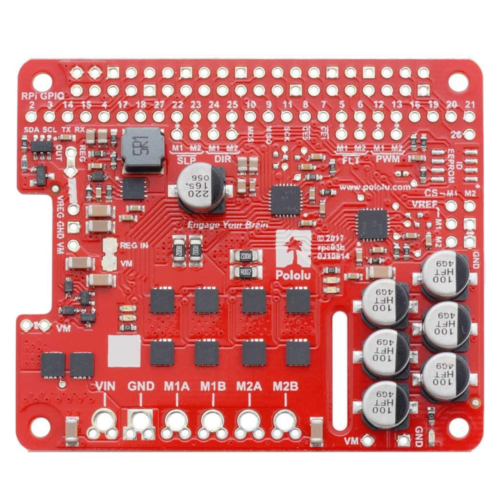
Power
An appropriate motor power supply should be connected to the motor driver’s large VIN and GND pads. The board includes a reverse-voltage protection circuit that helps prevent damage in case the motor power supply is connected backwards. The reverse-protected input voltage can be accessed for use in other circuits through the two pins labelled VM on the left side of the board.

By default, the motor power supply also feeds a 5 V, 2.5 A switching step-down regulator that provides power to the connected Raspberry Pi. An ideal diode circuit makes it safe to have a different power supply connected to the Raspberry Pi through its USB Micro-B receptacle while the motor driver is connected and powered.
If you want to power the Raspberry Pi separately, the regulator can be disconnected by cutting two exposed traces on the board: one between the surface-mount pads labelled “VM” and “REG IN”, and another between the two pins by the “REG OUT” label, as shown to the right. On the 24v14 and 24v18 versions, disconnecting the regulator increases the absolute maximum operating voltage of the board to 40 V.
Default pin mappings
This table shows how the Raspberry Pi’s GPIO pins are used to interface with the motor drivers:

Motor control options
With the PWM pin held low, both motor outputs will be held low (a brake operation). With PWM high, the motor outputs will be driven according to the DIR input. This allows two modes of operation: sign-magnitude, in which the PWM duty cycle controls the speed of the motor and DIR controls the direction, and locked-antiphase, in which a pulse-width-modulated signal is applied to the DIR pin with PWM held high.
In locked-antiphase operation, a low duty cycle drives the motor in one direction, and a high duty cycle drives the motor in the other direction; a 50% duty cycle turns the motor off. A successful locked-antiphase implementation depends on the motor inductance and switching frequency smoothing out the current (e.g. making the current zero in the 50% duty cycle case), so a high PWM frequency might be required.

PWM frequency
The motor driver supports PWM frequencies as high as 100 kHz, but note that switching losses in the driver will be proportional to the PWM frequency. Typically, around 20 kHz is a good choice for sign-magnitude operation since it is high enough to be ultrasonic, which results in quieter operation.
A pulse on the PWM pin must be high for a minimum duration of approximately 0.5 µs before the outputs turn on for the corresponding duration (any shorter input pulse does not produce a change on the outputs), so low duty cycles become unavailable at high frequencies. For example, at 100 kHz, the pulse period is 10 µs, and the minimum non-zero duty cycle achievable is 0.5/10, or 5%.
Fault conditions
The motor driver can detect several fault states that it reports by driving the FLT pin low; this is an open-drain output that should be pulled up to your system’s logic voltage. The detectable faults include short circuits on the outputs, under-voltage, and over-temperature. All of the faults disable the motor outputs but are not latched, meaning the driver will attempt to resume operation when the fault condition is removed (or after a delay of a few milliseconds in the case of the short circuit fault). The over-temperature fault provides a weak indication of the board being too hot, but it does not directly indicate the temperature of the MOSFETs, which are usually the first components to overheat, so you should not count on this fault to prevent damage from over-temperature conditions.
Remapping pins
All of the Raspberry Pi’s GPIO pins are broken out along a row of numbered through-holes just below the 40-pin GPIO connector. Each GPIO pin used by the board is connected from this row to the corresponding motor driver pin by a trace on the top side of the board spanning the pair of holes. If you want to remap one of these motor driver pins, you can cut its trace with a knife and then run a wire from the lower hole to a new GPIO pin.

Note that the default pin mappings were chosen so that the Raspberry Pi’s default GPIO pull-ups and pull-downs match the direction the motor driver pins are or should be pulled (up for SF, down for others); if you remap the motor driver pins without paying attention to this, you might encounter issues with pins being pulled the wrong way.
See the Raspberry Pi documentation for more about the default GPIO states.
Current sensing and limiting
The motor driver exposes current sensing and limiting pins that are not connected to the Raspberry Pi, but they are accessible through their own through-holes in case you want to use them in a more advanced application.

The driver has the ability to limit the motor current through current chopping: once the motor drive current reaches a set threshold, the driver goes into brake mode (slow decay) for about 25 μs before applying power to drive the motor again. This makes it more practical to use the driver with a motor that might only draw a few amps while running but can draw many times that amount (tens of amps) when starting.
For each motor channel, you can lower the limit by connecting an additional resistor between the VREF pin and the adjacent GND pin; the graph shows how the current limit relates to the VREF resistor value. Note that the current limiting threshold is not highly precise, and is less accurate at especially low settings (indicated by the dashed portion of the curve).
The driver’s current sense pins, labelled CS, output voltages proportional to the motor currents while the H-bridges are driving. The output voltage for this version is about 20 mV/A plus a small offset, which is typically about 50 mV.
Each CS output is only active while the corresponding H-bridge is in drive mode; it is inactive (low) when the channel is in brake mode (slow decay), which happens when the PWM input is low or when current limiting is active. Current will continue to circulate through the motor when the driver begins braking, but the voltage on the CS pin will not accurately reflect the motor current in brake mode. The CS voltage is used internally by the motor driver, so to avoid interfering with the driver’s operation, you should not add a capacitor to this pin or connect a load that draws more than a few mA from it.
Real-world power dissipation considerations
The MOSFETs can handle large current spikes for short durations (e.g. 100 A for a few milliseconds), and the driver’s current chopping will keep the average current under the set limit. The peak ratings are for quick transients (e.g. when a motor is first turned on), and the continuous rating is dependent on various conditions, such as the ambient temperature.
PWM'ing the motor will introduce additional heating proportional to the frequency. The actual current you can deliver will depend on how well you can keep the motor driver cool. The driver’s printed circuit board is designed to draw heat out of the MOSFETs, but performance can be improved by adding a heat sink or airflow. For high-current installations, the motor and power supply wires should also be soldered directly instead of going through the supplied terminal blocks, which are rated for up to 16 A.
Warning: This motor driver has no over-temperature shut-off. An over-temperature or over-current condition can cause permanent damage to the motor driver. You might consider using either the driver’s integrated current sense output (with an external ADC) or an external current sensor to monitor your current draw.
This product can get hot enough to burn under normal operating conditions. Take care when handling this product and other components connected to it.
Your payment information is processed securely. We do not store credit card details nor have access to your credit card information.