Challenger RP2040 WiFi (U.FL Connector)
Price:
Sale price
£9.80
Regular price
£14
Stock:
 Skip to content
Cart
Your cart is empty


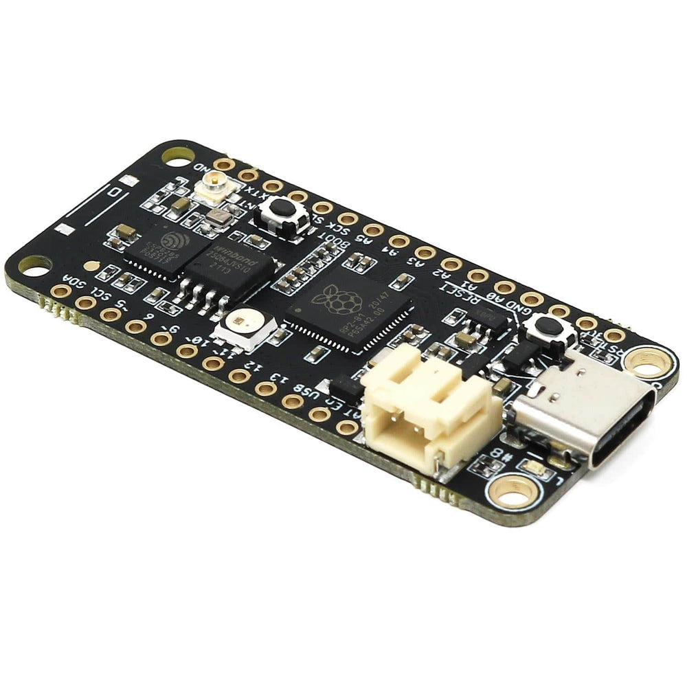
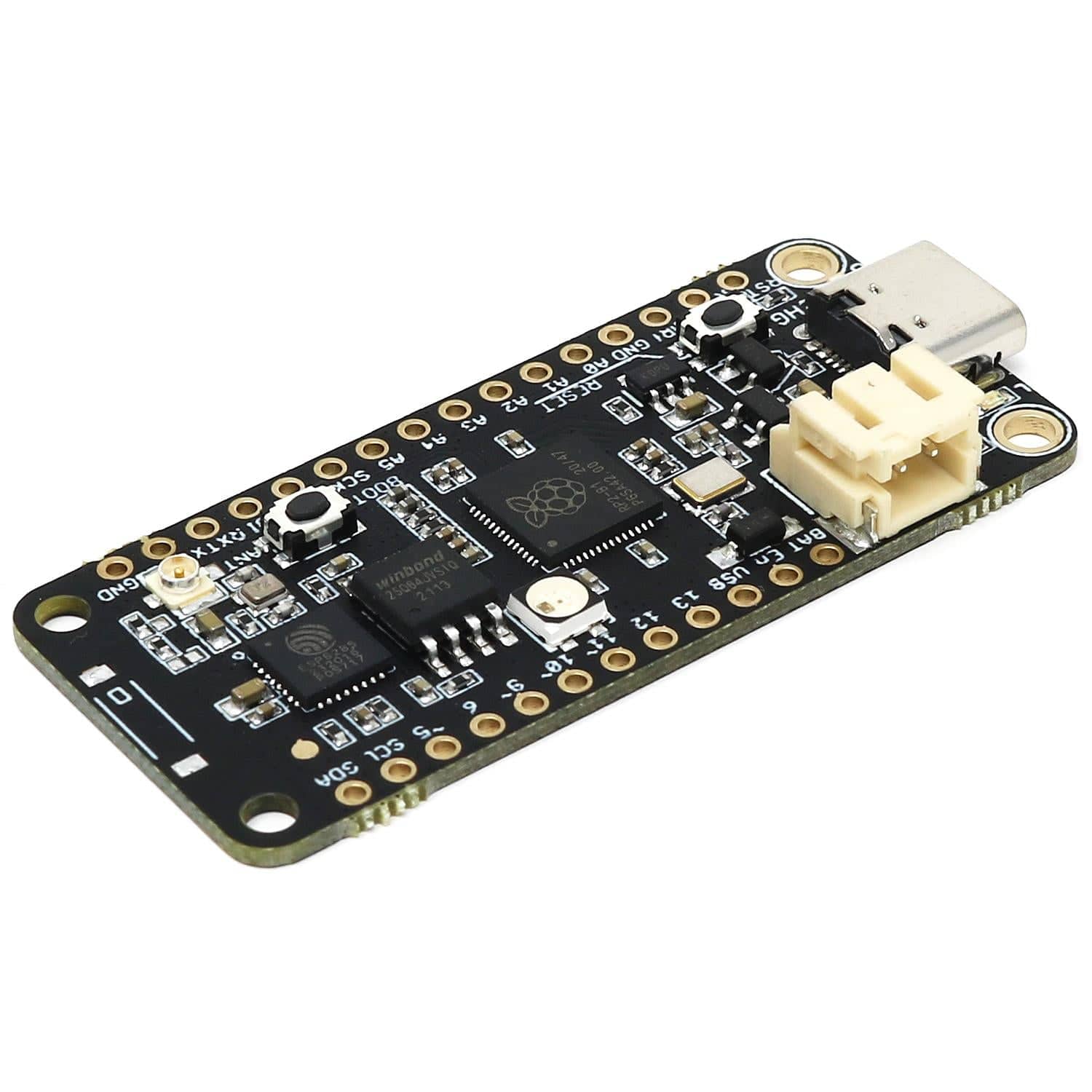
The iLabs Challenger RP2040 WiFi (with U.FL connector, no chip antenna) is an Arduino/Micropython compatible Adafruit Feather format microcontroller board based on the RP2040 chip from Raspberry Pi with WiFi onboard!
When iLabs designed this board they took their existing Challenger M0 WiFi board and replaced the SAMD21 microcontroller with the extremely powerful dual-core RP2040 Cortex-M0 device, which has 264KByte of SRAM internally and 8MByte of external FLASH memory.
We paired the RP2040 with a 8MByte high-speed flash capable of supplying data up to the maximum speed. The flash memory can be used both to store instructions for the microcontroller as well as data in a file system and having a file system available makes it easy to store data in a structured and easy to program approach.
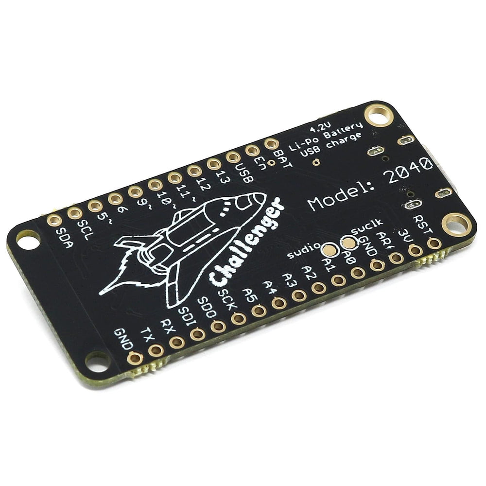
The device can be powered by a Lithium Polymer battery connected through a standard 2.0mm connector on the side of the board. An internal battery charging circuit allows you to charge your battery safely and quickly. The device is shipped with a programming resistor that sets the charging current to 250mA. this resistor can be exchanged by the user to either increase or decrease the charging current, depending on the battery that is being used.
The WiFi section on this board is based on the Espressif ESP8285 chip which basically is an ESP8266 with 1MByte FLASH memory integrated onto the chip making it a complete WiFi-only solution requiring very few external components.
The ESP8285 is connected to the microcontroller using a UART channel and the operation is controlled using a set of standardized AT-commands.
We also stock a version with an onboard chip antenna rather than a U.FL connector.
Just like the Challenger M0 WiFi this board has an ESP8285 WiFi chip. For those of you that are unfamiliar with this device, it is basically an ESP8266 device with an integrated 1MByte of flash memory. This allows us to have an AT command interpreter inside this chip that the main controller can talk to and connect to your local WiFi network. The communications channel between the two devices is an unused UART on the main controller and the standard UART on the ESP8285.
The ESP8285 chip comes pre-flashed with Espressif’s AT command interpreter stored in the internal 1MByte of the ESP8285. This interpreter supports most of the operating and sleep modes of the standard ESP8266 framework which makes it easy to work with. Talking to the device is as easy as opening the second serial port (Serial2), resetting the ESP8285 and start listening for events and sending commands
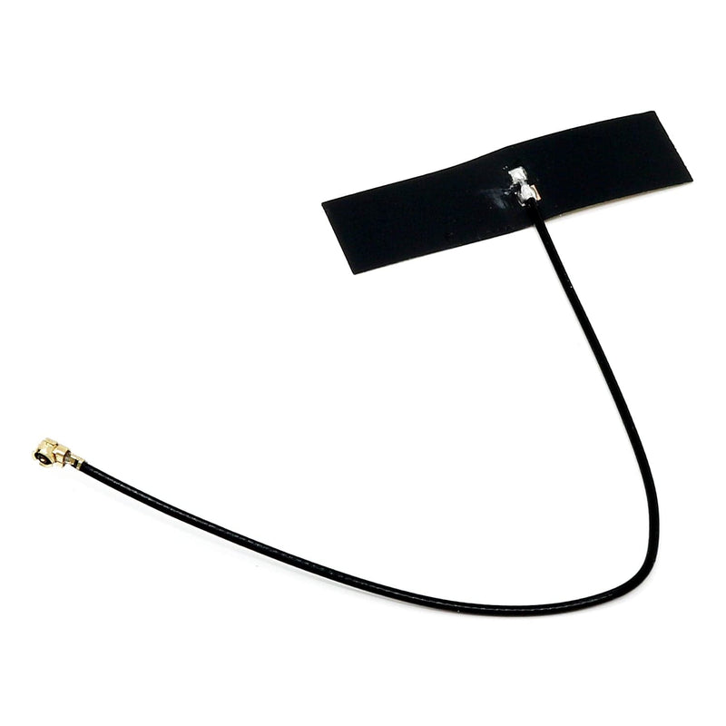
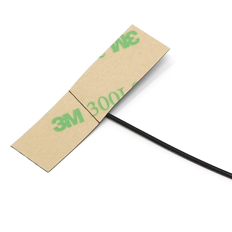
This version has a U.FL connector which requires an external antenna (no onboard chip antenna). You can use any 50ohm 2.45GHz antenna and it will work just fine.
We also stock a version with a built-in chip antenna and no U.FL connector.
The board can be powered from multiple sources. The most obvious way to run the board is by plugging it into a USB cable and attaching it to your computer. In this mode, you can write software and test the board with all its functionality.
You can also supply the board with 5V via the header connectors on the PWR pin.
There is a third way to supply the board too. This way is more invasive and will disable the onboard 3.3V power regulator. When doing this you will have to pull the EN header pin low and then supply your own 3.3V voltage on the 3.3V header pin. Please note that when disabling the onboard power regulator you will have to supply the 3.3V also when running the system on battery power.
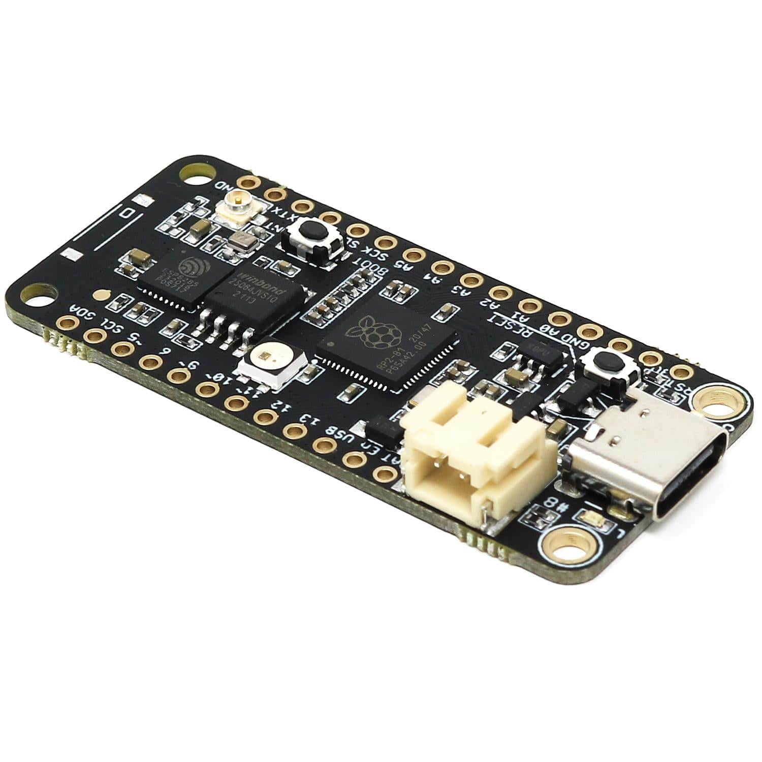
As described earlier the board can be powered by a LiPo battery. The battery can be connected using a standard 2.0mm JST connector through the battery connector on the right side of the board or if the battery is an integral part of the system that you are designing it is possible to connect the battery through the BAT pin instead.
Switching between the battery voltage and the applied USB voltage or external 5V is done seamlessly by the onboard circuitry.
Charging of the battery is achieved by either connecting a USB cable or by connecting a 5V power source to the header pin marked USB on the board. If you do this make sure you connect your voltage through a 1A schottky diode to avoid any excessive current draw in the system when the two levels are slightly different.
Please note that providing external charger circuitry could destroy the internal charger on the Challenger board.
On each side of the USB connector, there is a small indicator LED. The LED which is marked CHG is the charge control indicator. This red LED will light whenever the connected battery is being charged, and when the battery is fully charged the LED will turn off again. If you haven’t connected a battery to the board this LED will not come on at all.
On the other side of the USB connector, there is a user-programmable green LED. This LED is connected to pin D15 and can easily be controlled by the user program.
Finally, there is a NeoPixel-compatible LED on the board. This is an RGB LED with intensity control, run by a single GPIO pin on the board. There are several good example libraries that can be used to drive this LED.
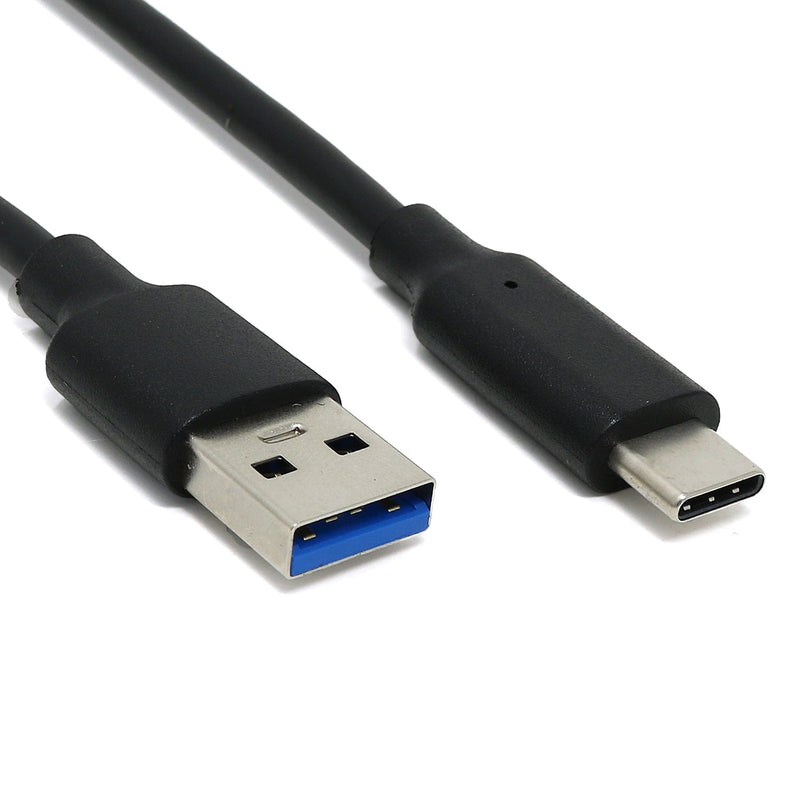
In recent years we have noticed that we are seeing more and more USB Type-C cables laying around the lab due to the fact that most new phones and accessories use them. So iLabs decided to go for a USB Type-C connector for this board. A bonus of this is that they are more durable and you don’t have to fiddle with the cable before plugging it in!
The board uses the second UART (UART 1) of the MCU to connect to the ESP8285 as well as two GPIO pins that allows the RP2040 to reset and put the ESP8285 in flash mode. The pins used are as follows.
The WiFi chip runs an internal AT interpreter, over the UART lines, to do all the wireless communication. It supports baud rates up to 921600 bits/s allowing the system to have a throughput of up to 500Kbit/s TCP traffic and up to 1MBit/s UDP messaging.
| Description | Value | Comment |
| Board Size | 50.80 mm x 22.86 mm x 3.20 mm | USB protrudes ~1mm |
| Main microcontroller | RP2040 from Raspberry Pi | 133MHz dual core Cortex M0 |
| SPI | One SPI channel configured | |
| I2C | One I2C channel configured | |
| UART | One UART channel configured | Second UART for the WiFi chip |
| Analog inputs | 4 analog input channels | |
| WLAN controller | ESP8285 from Espressif | 160MHz single core Tensilica L106 |
| FLASH Memory | 8MByte 133 MHz | |
| SRAM Memory | 264KByte | Divided into 6 banks |
| USB 2.0 controller | Up to 12MBit/s full speed | Integrated USB 1.1 PHY |
| JST Battery connector | 2.0mm pitch | |
| Onboard LiPo charger | 250mA standard charge current | |
| NeoPixel-compatible LED | RGB LED |
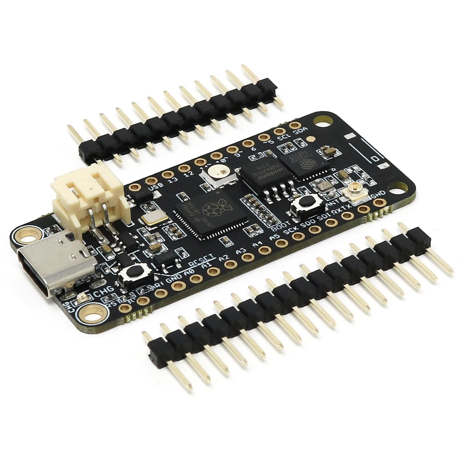
The RP2040 has a number of communication channels that have been routed out to the side (header connector) connectors:
The pin chart below shows the placement of all pins and their respective functions. When working in an Arduino environment (or Platform IO) use the blue pins when writing your code, and when working with CircuitPython use the orange marked pin assignments:

iLabs teamed up with Earle F. Philhower over at his Github page to provide Arduino support for their RP2040/Pico based boards. All instructions on how to install the board support package as well as multiple examples on how to use the Raspberry Pi Pico processor.
The Challenger RP2040 WiFi board is fully compatible with both the micropython package found at the Raspberry Pi site as well as Adafruit's CircuitPython. Instructions on how to install the python interpreter of your choice are available on the respective websites.
Your payment information is processed securely. We do not store credit card details nor have access to your credit card information.